Placement of scenery objects in the tutorial level:
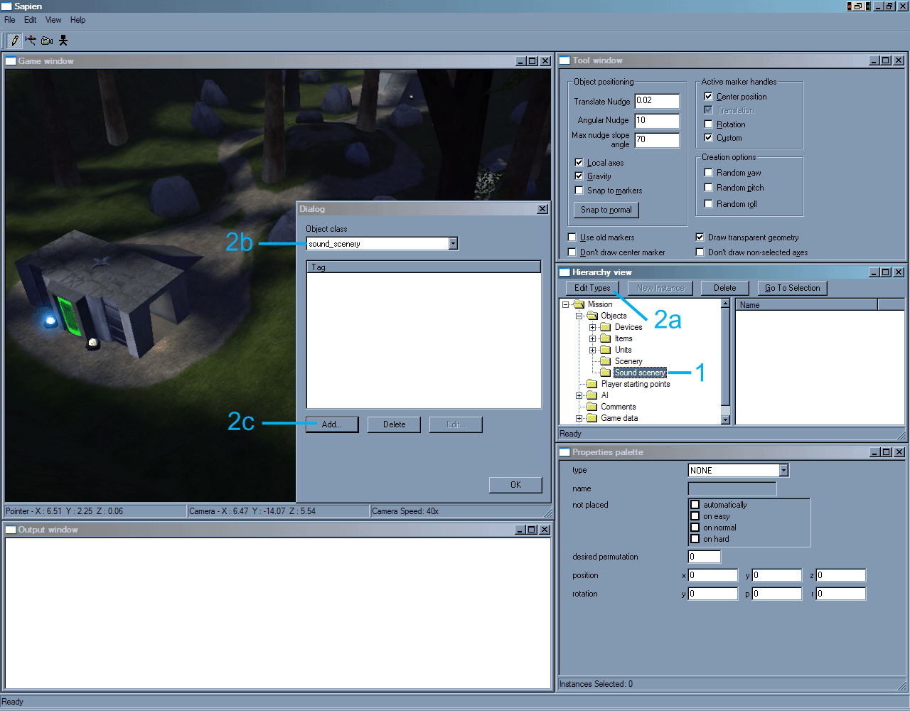
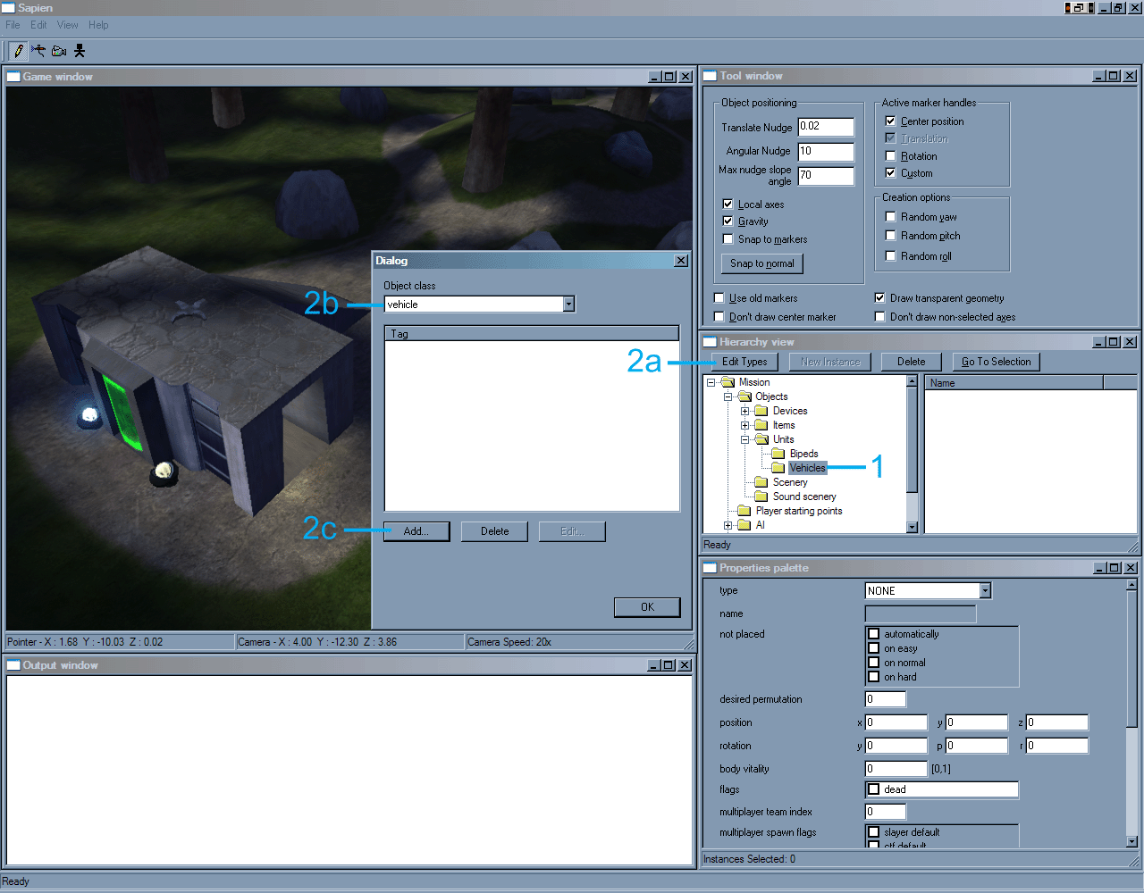
1) Go to the Hierarchy view window. In the Hierarchy tree expand the "Objects" branch and select the "Scenery" objects group.
2) Currently, the Scenery "palette" is empty. A scenery palette will be created that will contain the scenery objects that will be placed in the level. To create a scenery palette follow the procedures below.
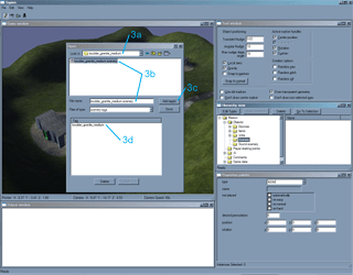
a) Click on Edit Types in the Hierarchy view window. The Dialog window will appear which shows the current scenery object palette, in this case it is empty.
b) The current Object class is set to scenery since the Dialog window was accessed through the Scenery group in the Hierarchy tree.
c) Click on the "Add..." button. An Open dialog window will appear.
The first image further explains the above procedures.
There are many scenery tags available for usage in a level. The majority of .scenery tags are located in the main scenery tags directory (i.e. Halo\tags\scenery). It is also quite common for individual level directories to contain their own custom scenery directories and associated .scenery tags. It is suggested that the user explore all the level directories to discover what .scenery tag resources are available.
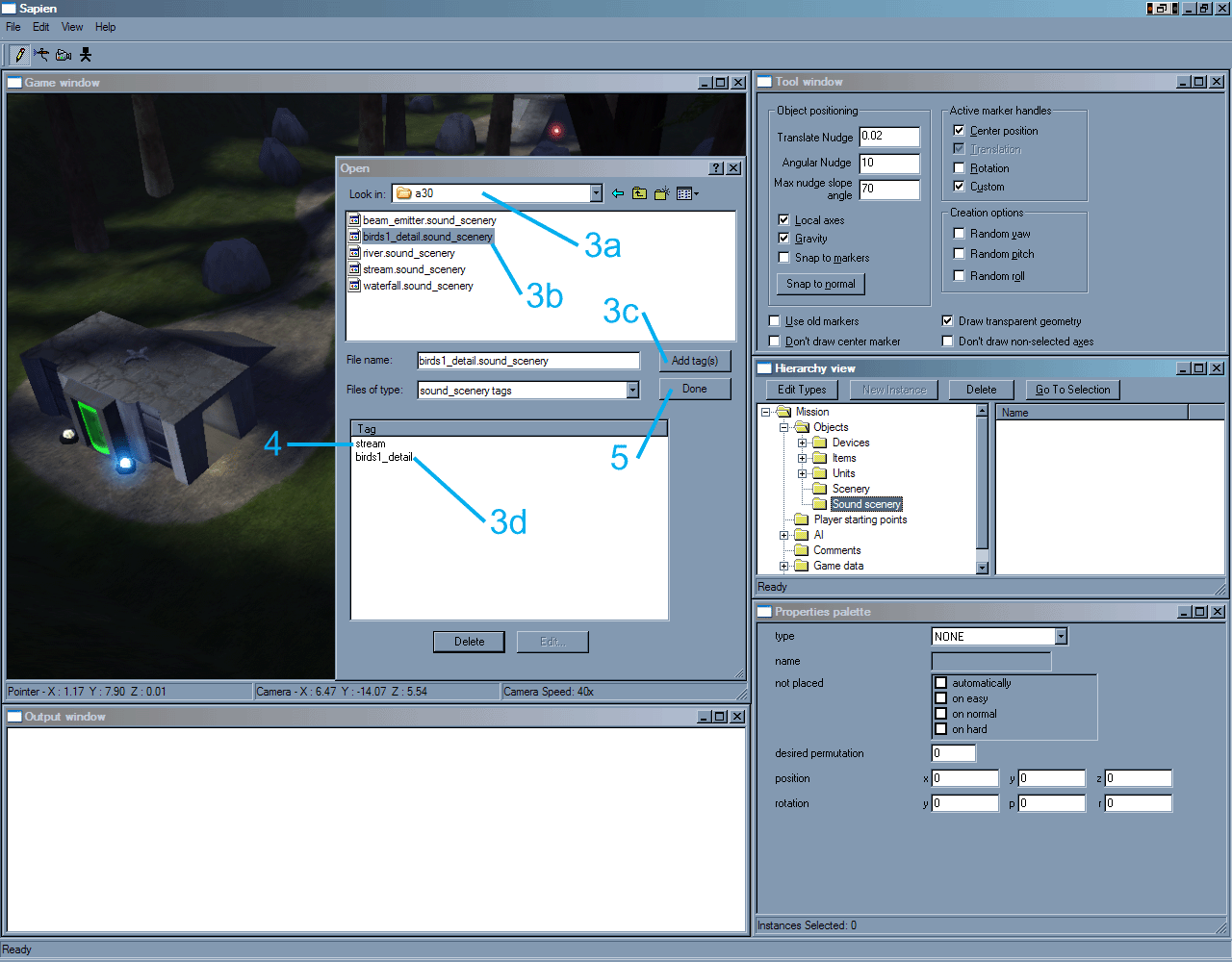
3) Some rocks are going to be added for use in the level and therefore must be added to the scenery palette. Follow the steps below to add the rock scenery tags to the level.
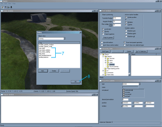
In the Open dialog window, go to the scenery tags directory.
a) In the scenery directory enter the "rocks" directory. In the rocks directory select the "boulder_granite_medium" directory.
b) Select the "boulder_granite_medium.scenery" tag.
c) Click on the Add tag(s) button.
d) The "boulder_granite_medium" object should now appear in the Tag listing at the bottom of the Open dialog.
The second image further explains the above procedures.
4) The procedures listed in 3a through 3d were then used to add the "boulder_granite_small.scenery" tag.
5) Once the "boulder_granite_small.scenery" tag is added, click the Done button
The third image further explains the above procedures.
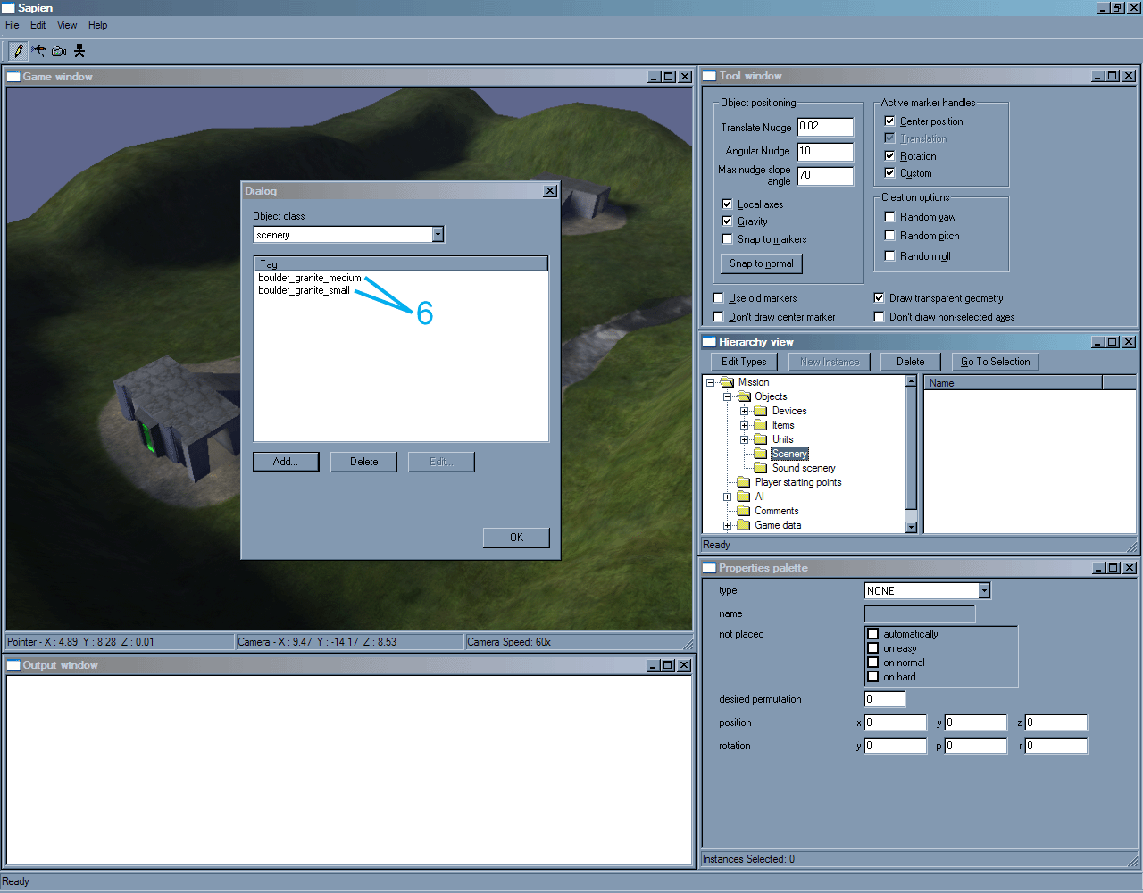
6) The Dialog window for scenery objects should now be visible again. The "boulder_granite_medium" and "boulder_granite_small" tags should appear in the Tag window.
The fourth image further explains the above procedures.
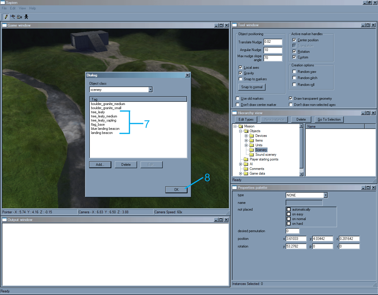
7) The procedures above were followed to add the additional scenery objects for trees, beacons, and the flag stand scenery objects listed below: The following tree scenery tags are found under their respective subdirectories under the "tree" subdirectory under the tags main directory.
tree_leafy
tree_leafy_medium
tree_leafy_sapling
The "flag_base" scenery object is found under the "flag_base" scenery tag directory under the tags main directory.
flag_base
The blue landing beacon and red landing beacon (which is just labeled "landing beacon") scenery tags are each found under their respective directories under the tags main directory.
blue landing beacon landing beacon
8) When all the listed scenery object tags have been added to the palette, click the OK button.
The fifth image further explains the above procedures and shows the final scenery palette as it appears in the Dialog window for scenery tag objects.
With a scenery palette created, scenery can now be placed in the level.
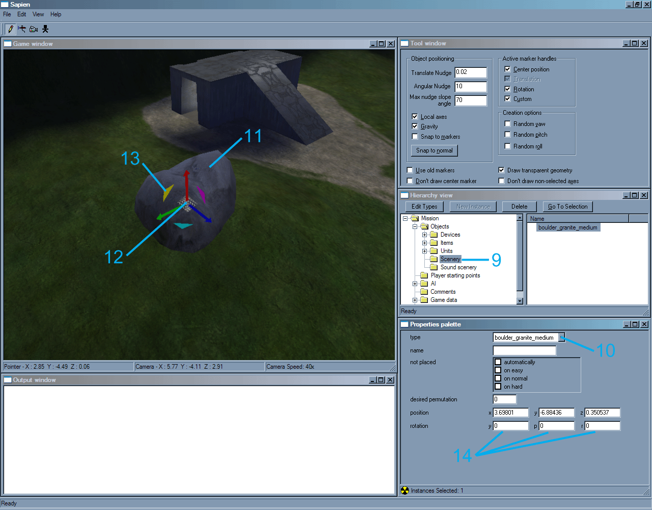
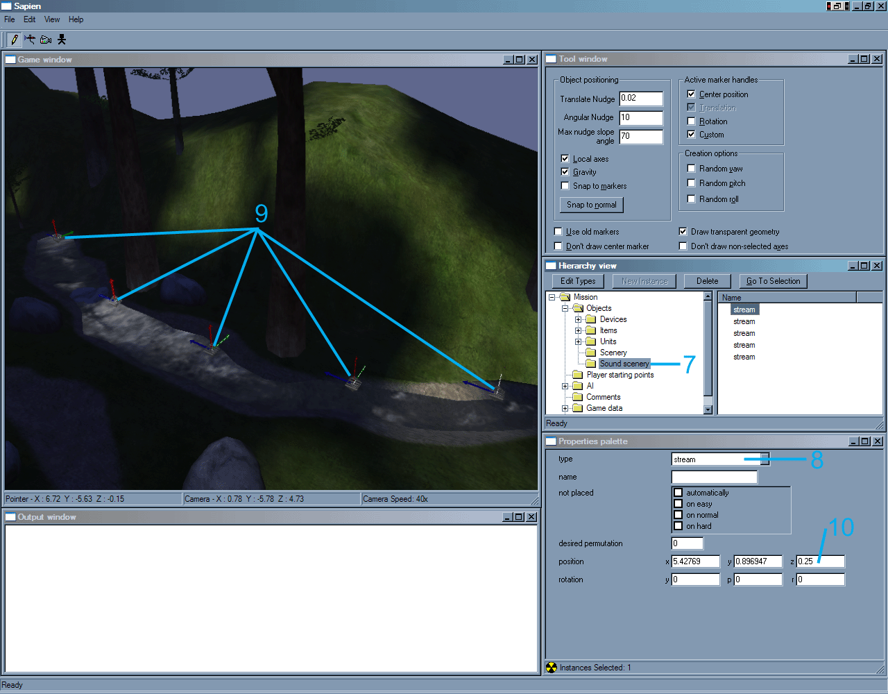
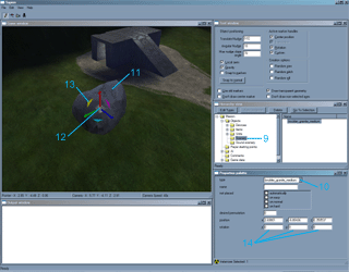
9) Make sure that the "Scenery" group in the Hierarchy tree is selected. In the Game Window press the Right Mouse Button to place a scenery object.
10) The scenery object will most likely appear as just a marker, it must have a scenery object type set for it that corresponds to one of the scenery objects or tags in the scenery palette.
In the Properties palette window use the pull down menu that is associated with the "type" field to select "boulder_granite_medium".
11) The marker in the Game Window should now appear as the selected object, in this case the "boulder_granite_medium" scenery model or object.
NOTE: Every subsequent Right Mouse Button click will create the currently selected object in the Game Window unless the "type" is changed or an object is selected in the right pane of the Hierarchy view window.
IMPORTANT: As objects are added, if the model associated to the .scenery object has several different variations or permutations of the model, these different variations will be randomly selected as objects are placed.
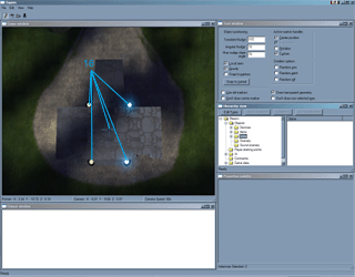
12) To move a placed object select the "center marker" by clicking on it with the Left Mouse Button, then while still holding down the Left Mouse Button move the object around the level.
13) To change the orientation of the object (the rotation angles for the object, Yaw, Pitch, and Roll) click on the "rotation markers" with the Left Mouse Button, then while still holding down the Left Mouse Button move the mouse to change the angle.
14) The rotation angle or orientation of the object can also be manually typed in by entering values into the y, p, and r fields that are found under the "rotation" section for the object in the Properties palette.
The sixth image further explains the above procedures.
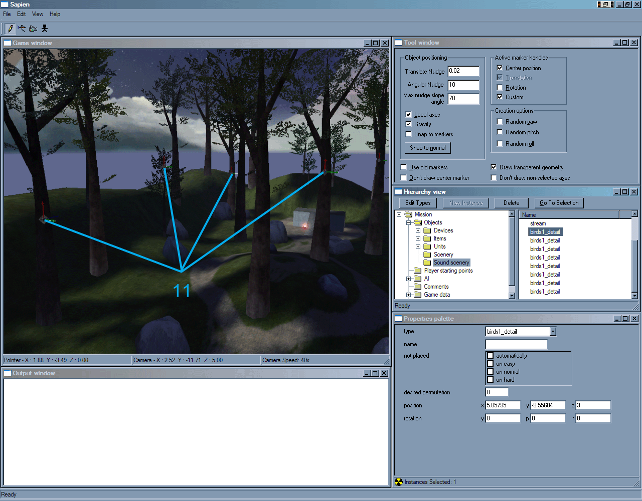
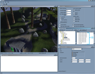
15) Additional boulder_granite_medium scenery objects were placed and arranged in the level as well as boulder_granite_small, tree_leafy, tree_leafy_medium, and tree_leafy_sapling scenery objects.
The scenery objects and player spawn points were adjusted so as not to interfere with each other.
In addition, since many of the scenery objects placed are set up to block light, the radiosity process was run again to make sure the lighting was correct. The lighting in the level should be updated anytime model objects are added or adjusted.
The seventh image further explains the above procedures and shows the placement positions and orientations of the scenery objects.
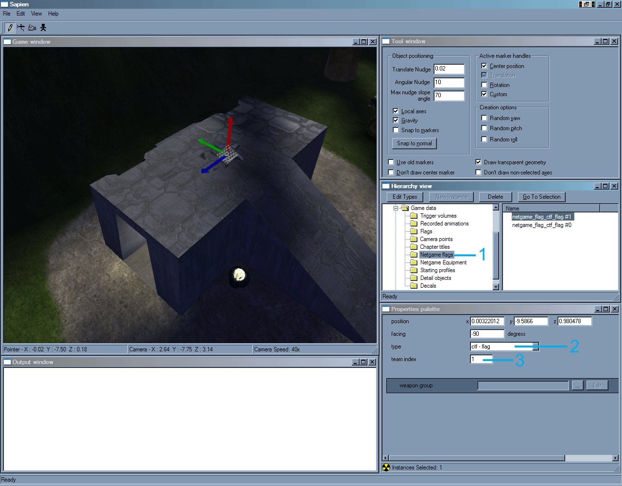
16) The next scenery objects that were added were two flag bases (flag_base) and red beacons (landing beacon) and blue beacons (blue landing beacon) to help distinguish the bases.
The flag_base scenery object has nothing to do with the actual flag game code and behaviors. It is placed at the spot where the flag will be placed and serves as a visual indicator to the players where the flag should be taken to capture or complete an objective. The actual netgame flag for the CTF flag will handle the game code.
The eighth image further explains the above procedures and shows the placement positions and orientations of the flag and colored beacon scenery objects. |

Click to Open Larger Image in New Window

Click to Open Larger Image in New Window

Click to Open Larger Image in New Window

Click to Open Larger Image in New Window
Click to Open Larger Image in New Window
Click to Open Larger Image in New Window
Click to Open Larger Image in New Window
Click to Open Larger Image in New Window |