Population


The following section covers the population or placement of objects in the level using Sapien.  Tutorials and information cover an overview of the Sapien tool, player spawn point placement and information, scenery object implementation and placement, vehicle and weapon implementation and placement, netgame flags information and placement, and the manipulation and setting of BSP portal data including fog, sounds and weather effects.


Sapien Overview


Sapien is used to place objects in the level The placement of objects in a level is sometimes referred to as "population" The objects that are placed in the level include objects for aesthetics and game play (scenery objects such as trees, rocks, bushes, etc...) as well as objects that are required for the level to run and operate properly in the game (netgame flags, netgame equipment, spawn points, etc..).

Sapien has a graphical interface that contains a 3D window (the Game Window) that renders the game including the level bsp, models, and vehicles The Game Window also runs other game systems as well and plays sounds and runs physics

Sapien does not have any form of "undo" functionality Therefore, it is HIGHLY recommended that the .scenario tag be saved and saved often Saving off sequential versions of the file is also HIGHLY recommended (i.e. tutorial_01.scenario, tutorial_02.scenario, etc...)

Halo has a lot of objects that can be used in a level These objects all exist as a data tag To help in the organization of objects or tags for placement in the game level using Sapien, a subset of objects or tags is created for certain object types or groups in the hierarchy This specific set of tags is called a "palette" Objects or tags are then selected from the palette for placement in the level The palette can have items added or removed at any time Removal of an item reference from the palette does NOT remove the item marker from the level, instead the item is set to NONE so that the item will no longer appear in the level This empty item marker should be removed from the level.

The images and discussions below will explain the basics of the Sapien Graphical User Interface.


Overview of the Sapien Graphical User Interface:

Go to the main Halo directory.  In the root directory is where all the Halo tools exist, there should be a program file called sapien.exe.

Run Sapien.  When Sapien loads, an Open dialog window will appear.  Use this dialog to load the tutorial.scenario tag.

Sapien will now load.  Sapien runs many of the same systems as the game so give it time to load, especially for larger levels. 

The tutorial level should now appear in the Game Window.


Click to Open Larger Image in New Window

The following descriptions will point out a particular section or feature of the user interface and then provide a description.  The descriptions are numbered and appropriately labeled in the above image of Sapien.

1) Game Window - The Game Window is the main interface when interacting with objects in the level.  Objects can be chosen in this window as well as selected in the Hierarchy view.  As stated before, the Game Window runs or uses many of the same systems that the full game does.

2) Output Window - This is unused in the build of Sapien that will be used.

3) Tool Window - This window contains properties that can be enabled or disabled to aid in the placement of certain objects. 

The most commonly used settings, or options that are modified the most, are the options under the Active marker handles section and the Don't draw center marker option.

4) Hierarchy view - The Hierarchy view displays all the objects currently placed in the game and organizes them by type.  The left pane of the window shows the Hierarchy tree and currently selected type, and the right pane shows the objects of this selected group or type that are currently placed in the level.

5)  The following sub-objects exist under the main Mission object.

a) Objects - The following are included under the Objects tree:

Devices (Machines, Controls, Light fixtures, and Device groups) - These are special objects that can be placed in the level.  For multiplayer levels, the light fixtures are the most commonly used.  Other things like Machines, Controls, and Device groups are for single player.

Items (Equipment and weapons) - Items are game objects that can be placed in the level. The equipment and weapons in this group are for single player only.  Multiplayer equipment and weapons are placed using Netgame equipment (see below under the Game Data group).

Units (Bipeds and Vehicles) -  Units represent game objects that can be placed in the level. The Bipeds group is unused in multiplayer.  Multiplayer vehicles are placed using the Vehicles palette created in this group. 

Scenery - Model objects that can be placed in the level.  Scenery objects (.scenery tags) are placed using the palette created for this group.

Sound scenery - Sound scenery objects (.sound_scenery tags) are placed using the palette created for this group.  Sound scenery are objects that can be placed in the level to add ambient sounds.
b) Player starting points - This group allows the placement of player spawn points for both single and multiplayer levels

c) AI - This group only applies to single player and will not be discussed.

d) Comments - Not relevant to multiplayer levels.

e) Game data - The following are included under the Game data tree:

Trigger volumes - Not applicable to multiplayer.

Recorded animations - Not applicable to multiplayer.

Flags - Not applicable to multiplayer.

Camera points - Not applicable to multiplayer.

Chapter titles - Not applicable to multiplayer.

Netgame flags - These are heavily used in the creation of a multiplayer level.  The placement and definition of the type of netgame flag is used to create the multiplayer game objects and objectives such as the Oddball, Flag for CTF, etc...

Netgame Equipment - These are heavily used in the creation of a multiplayer level.  The placement and definition of netgame equipment objects is used to place the weapons and power ups in the level as well as in what game types these weapons should spawn.

Starting profiles - Not applicable to multiplayer, the player starting weapons and grenades are handled in the Starting Equipment section in the .scenario tag.  (See the section Setting Level Attributes Using Guerilla under Level Data Manipulation in Guerilla for setting the player starting profile for multiplayer and the multiplayer game types.)

Detail objects - Not used in multiplayer levels.

Decals - Decals can be used in multiplayer levels, but it is recommended that non-solid faces or polygons be placed in the level to achieve the same result.  Decals can cause a performance hit in Halo. 
f) Cluster properties - Cluster properties refer to the settings or attributes that can be applied to a portal in the .scenario_structure_bsp.  Cluster properties includes the following groups:

Palettes - The palette group includes the Fog palette, Background sound palette, Sound environment palette and Weather palette.  Palettes are used to create a set of tags that are referenced for the level.  It is these references that are used to assign certain attributes to portals or clusters.

Fog - When the camera position is in a particular portal or cluster, the fog reference can be changed\applied or viewed here.

Background sound - When the camera position is in a particular portal or cluster, the Background sound (ambient sounds) reference can be changed\applied or viewed here.

Sound environment - When the camera position is in a particular portal or cluster, the sound environment (environmental audio effects) reference can be changed\applied or viewed here.

Weather - When the camera position is in a particular portal or cluster, the weather reference can be changed\applied or viewed here.
6) Properties palette - The Properties palette window displays the object properties for the currently selected object.  The type of object can be changed or chosen in this display as well as various other properties such as the position and rotation of the object, and spawn flags that set various attributes for the object.


Sapien Controls


The table below lists the basic controls and key commands used in Sapien.


Control/Keyboard Key Action/Functionality
 
Left Mouse Button Selects objects in the Game Window.

Holding down the Left Mouse Button over and object or object handle and dragging or moving the mouse will move the selected object.

If an object is selected in the Hierarchy view, double clicking on the object in the right pane of the Hierarchy view or window will move the Game Window camera to this object.
Right Mouse Button Places a new instance of the selected object.
Middle Mouse Button When the Middle Mouse Button is held while in the Game Window, the camera controls are able to be used.
 
Mouse Movement Left/Right When used with the Middle Mouse Button held down, this rotates the camera yaw in the Game Window.
W When used with the Middle Mouse Button held down, this rotates the camera pitch in the Game Window.
 
W When used with the Middle Mouse Button held down, this moves the camera forward in the Game Window.
A When used with the Middle Mouse Button held down, this moves the camera backwards in the Game Window.
S When used with the Middle Mouse Button held down, this pans the camera left in the Game Window.
D When used with the Middle Mouse Button held down, this pans the camera right in the Game Window.
R When used with the Middle Mouse Button held down, this moves the camera along the Z-Axis in the positive direction (up) in the Game Window.
F When used with the Middle Mouse Button held down, this moves the camera along the Z-Axis in the negative direction (down) in the Game Window.
 
SHIFT Tapping the SHIFT key changes the camera movement speed in the Game Window.
DELETE Delete the selected the object.
~ This opens the developer console in the Game Window.


Sapien Setup and Configuration


Arrange the windows in Sapien in a useful configuration.  The images shown in the examples and tutorials below show one window layout that is fairly efficient for multiplayer level design.

The window layouts and configuration are saved in the Windows System Registry so that Sapien does not have to be configured every time it is loaded.


Object Placement in Sapien


The following sections contain tutorials and examples that will demonstrate the placement of various objects and object types in the level.


Player Spawn Point Placement

The following section contains tutorials and examples that will demonstrate the placement of multiplayer spawns in the level.


Placement of multiplayer spawns in the tutorial level:

Go to the main Halo directory.  In the root directory is where all the Halo tools exist, there should be a program file called sapien.exe.

Run Sapien.  When Sapien loads, an Open dialog window will appear.  Use this dialog to load the tutorial.scenario tag.

Sapien will now load.  Sapien runs many of the same systems as the game so give it time to load, especially for larger levels.

The tutorial level should now appear in the Game Window.

1) Position the camera in the Game Window so that the Blue Base is in view.

2) Select "Player starting points" in the Hierarchy view window.

3) 8 player spawn points will now be placed for the Blue Team.

In the Game Window, click the Right Mouse Button to place or create  the spawn points. 

Click on the spawn point center markers and drag the points to move them around the level.  Notice that the objects conform to the level geometry.

See the Multiplayer Level Design Technical Rules and Guidelines section in the General Level Design Information section under General Reference for rules and suggestions on player spawn placement.

4) Once the 8 player spawn points are placed, select each spawn point (this is more easily done using the right pane in the Hierarchy view) and go to the Properties palette window and enter a "1" in the "team index" field.  A "team index" value of "0" designates a Red Team spawn point, and a value of "1" designates a Blue Team spawn point.

5) These particular spawn points will be set up such that they can be used to spawn players for all game types. 

In the Properties palette window, use the pull down menu for the "type 0" field to select the setting "all games".

The first image further explains the above procedures.


6) Follow procedures 1 - 5 to place spawns at the Red Base.

7) Make sure the spawn points are set up for the Red Team.  

A "team index" value of "0" designates a Red Team spawn point.

8) Set the "facing" value to 180 degrees.  This value can be found in the Properties palette for each spawn point.  This makes the player spawn facing the center of the level.

The second image further explains the above procedures.


Even though this level is only large enough for 8 players total, there are now enough spawn points for a 16 player multiplayer game of Halo for all the available game types. 

To add some variation to the places where the player can spawn, some additional spawn points are going to be added for certain game modes.

9) 2 additional spawn points were added to each side of the level for a total of 4 new spawn points.  1 spawn point on each side was set to the Red Team and 1 spawn point on each side was set to the Blue Team.

10 The angle that the player faces when spawning was adjusted to face in towards the center.  This can be accomplished 2 ways:

a) by typing a "facing" value in Properties palette window

b) by clicking on the rotation marker handle and using the mouse to rotate the angle for the spawn point.

11) These spawn points will only spawn players when the Slayer and Oddball game modes are being played.

The "type 0" field is set to "slayer" and the "type 1" field is set to "oddball". 

As demonstrated, spawn points can be set up to work for any number of game modes or combination of game modes.

The third image further explains the above procedures.


Click to Open Larger Image in New Window


Click to Open Larger Image in New Window


Click to Open Larger Image in New Window


Scenery Object Placement

The following section contains tutorials and examples that will demonstrate the creation of a scenery palette and placement of scenery objects in the level.


Placement of scenery objects in the tutorial level:

1) Go to the Hierarchy view window. In the Hierarchy tree expand the "Objects" branch and select the "Scenery" objects group.

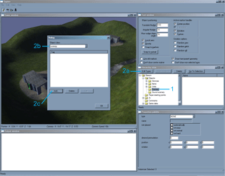
2) Currently, the Scenery "palette" is empty. A scenery palette will be created that will contain the scenery objects that will be placed in the level. To create a scenery palette follow the procedures below.

a) Click on Edit Types in the Hierarchy view window. The Dialog window will appear which shows the current scenery object palette, in this case it is empty.

b) The current Object class is set to scenery since the Dialog window was accessed through the Scenery group in the Hierarchy tree.

c) Click on the "Add..." button. An Open dialog window will appear.

The first image further explains the above procedures.


There are many scenery tags available for usage in a level. The majority of .scenery tags are located in the main scenery tags directory (i.e. Halo\tags\scenery). It is also quite common for individual level directories to contain their own custom scenery directories and associated .scenery tags. It is suggested that the user explore all the level directories to discover what .scenery tag resources are available.

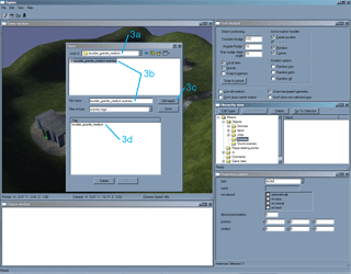
3) Some rocks are going to be added for use in the level and therefore must be added to the scenery palette. Follow the steps below to add the rock scenery tags to the level.

In the Open dialog window, go to the scenery tags directory.

a) In the scenery directory enter the "rocks" directory. In the rocks directory select the "boulder_granite_medium" directory.

b) Select the "boulder_granite_medium.scenery" tag.

c) Click on the Add tag(s) button.

d) The "boulder_granite_medium" object should now appear in the Tag listing at the bottom of the Open dialog.

The second image further explains the above procedures.


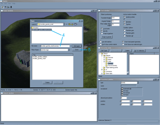
4) The procedures listed in 3a through 3d were then used to add the "boulder_granite_small.scenery" tag.

5) Once the "boulder_granite_small.scenery" tag is added, click the Done button

The third image further explains the above procedures.


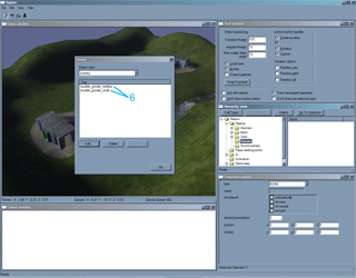
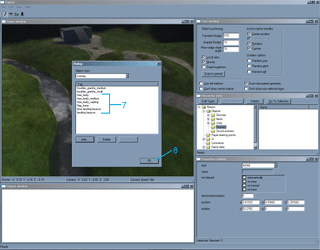
6) The Dialog window for scenery objects should now be visible again. The "boulder_granite_medium" and "boulder_granite_small" tags should appear in the Tag window.

The fourth image further explains the above procedures.


7) The procedures above were followed to add the additional scenery objects for trees, beacons, and the flag stand scenery objects listed below: The following tree scenery tags are found under their respective subdirectories under the "tree" subdirectory under the tags main directory.

tree_leafy
tree_leafy_medium
tree_leafy_sapling

The "flag_base" scenery object is found under the "flag_base" scenery tag directory under the tags main directory.

flag_base

The blue landing beacon and red landing beacon (which is just labeled "landing beacon") scenery tags are each found under their respective directories under the tags main directory.

blue landing beacon landing beacon

8) When all the listed scenery object tags have been added to the palette, click the OK button.

The fifth image further explains the above procedures and shows the final scenery palette as it appears in the Dialog window for scenery tag objects.


With a scenery palette created, scenery can now be placed in the level.

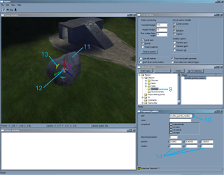
9) Make sure that the "Scenery" group in the Hierarchy tree is selected. In the Game Window press the Right Mouse Button to place a scenery object.

10) The scenery object will most likely appear as just a marker, it must have a scenery object type set for it that corresponds to one of the scenery objects or tags in the scenery palette.

In the Properties palette window use the pull down menu that is associated with the "type" field to select "boulder_granite_medium".

11) The marker in the Game Window should now appear as the selected object, in this case the "boulder_granite_medium" scenery model or object.

NOTE: Every subsequent Right Mouse Button click will create the currently selected object in the Game Window unless the "type" is changed or an object is selected in the right pane of the Hierarchy view window.

IMPORTANT: As objects are added, if the model associated to the .scenery object has several different variations or permutations of the model, these different variations will be randomly selected as objects are placed.

12) To move a placed object select the "center marker" by clicking on it with the Left Mouse Button, then while still holding down the Left Mouse Button move the object around the level.

13) To change the orientation of the object (the rotation angles for the object, Yaw, Pitch, and Roll) click on the "rotation markers" with the Left Mouse Button, then while still holding down the Left Mouse Button move the mouse to change the angle.

14) The rotation angle or orientation of the object can also be manually typed in by entering values into the y, p, and r fields that are found under the "rotation" section for the object in the Properties palette.

The sixth image further explains the above procedures.


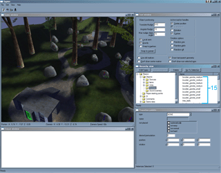
15) Additional boulder_granite_medium scenery objects were placed and arranged in the level as well as boulder_granite_small, tree_leafy, tree_leafy_medium, and tree_leafy_sapling scenery objects.

The scenery objects and player spawn points were adjusted so as not to interfere with each other.

In addition, since many of the scenery objects placed are set up to block light, the radiosity process was run again to make sure the lighting was correct. The lighting in the level should be updated anytime model objects are added or adjusted.

The seventh image further explains the above procedures and shows the placement positions and orientations of the scenery objects.


16) The next scenery objects that were added were two flag bases (flag_base) and red beacons (landing beacon) and blue beacons (blue landing beacon) to help distinguish the bases.

The flag_base scenery object has nothing to do with the actual flag game code and behaviors. It is placed at the spot where the flag will be placed and serves as a visual indicator to the players where the flag should be taken to capture or complete an objective. The actual netgame flag for the CTF flag will handle the game code.

The eighth image further explains the above procedures and shows the placement positions and orientations of the flag and colored beacon scenery objects.


Click to Open Larger Image in New Window


Click to Open Larger Image in New Window


Click to Open Larger Image in New Window


Click to Open Larger Image in New Window


Click to Open Larger Image in New Window


Click to Open Larger Image in New Window


Click to Open Larger Image in New Window


Click to Open Larger Image in New Window

Scenery Object Placement

Sound scenery are just objects that have a sound attached to them and are used to place ambient sounds in the level.  Sound scenery objects do not render, they are merely points in the level from which sound originates.

The following section contains tutorials and examples that will demonstrate the creation of a sound scenery palette and placement of sound scenery objects in the level.


Placement of sound scenery objects in the tutorial level:

1) Go to the Hierarchy view window.  In the Hierarchy tree expand the "Objects" branch and select the "Sound scenery" objects group.

2) Currently, the "Sound scenery" "palette" is empty.  A sound scenery palette will be created that will contain the sound scenery objects that will be placed in the level.  To create a sound scenery palette follow the procedures below.

a) Click on Edit Types in the Hierarchy view window.  The Dialog window will appear which shows the current sound scenery object palette, in this case it is empty.

b) The current Object class is set to sound_scenery since the Dialog window was accessed through the "Sound scenery" group in the Hierarchy tree.

c) Click on the "Add..." button.  An Open dialog window will appear.

The first image further explains the above procedures.


There are many sound scenery tags available for usage in a level.  The majority of .sound_scenery tags are located in the subdirectories found under the  Halo\tags\sound\sfx\ambience directory.  It is also quite common for individual level directories to contain their own custom sound directories that contain .sound_scenery tags.  It is suggested that the user explore all the level directories to discover what .sound_scenery tag resources are available.

The sound of birds and the sounds for a running stream will be added to the level. Therefore, the appropriate .sound_scenery tags must be added to the sound scenery palette. 

3) Follow the steps below to add the "birds1_detail.sound_scenery",  "teleporter_loop.sound_scenery" and the "stream.sound_scenery" tags to the level.

In the Open dialog window, go to the "sound\sfx\ambience\" tags directory located under the main tags directory.

a) In the "ambience" directory enter the "a30" directory. 

b) Select the "birds1_detail.sound_scenery" tag.

c) Click on the Add tag(s) button. 

d) The "birds1_detail" object should now appear in the Tag listing at the bottom of the Open dialog.

4) The procedures listed in 3a through 3d were then used to add the "stream.sound_scenery" tag and the "teleporter_loop.sound_scenery"

The "teleporter_loop.sound_scenery" is located in the "Halo\tags\sound\sfx\ui" directory.

5) Once the "stream.sound_scenery" and "teleporter_loop.sound_scenery" tags are added, click the Done button

The second image further explains the above procedures.


6)  The Dialog window for scenery objects should now be visible again.  The "stream.sound_scenery", "birds1_detail.sound_scenery" and "teleporter_loop.sound_scenery" tags should appear in the Tag window.

Click the OK button.

The third image further explains the above procedures.


With a sound scenery palette created, sound scenery can now be placed in the level.

7) Make sure that the "Sound scenery" group in the Hierarchy tree is selected.  In the Game Window, press the Right Mouse Button to place a sound scenery object on the stream geometry in the level.

8) The sound scenery object will appear as just a marker.  The sound scenery object will also be set to NONE.  It must have a sound scenery object type set for it that corresponds to one of the sound scenery objects or tags in the sound scenery palette.

In the Properties palette window use the pull down menu that is associated with the "type" field to select "stream". 

9) Place a total of 5 stream.sound_scenery objects along the length of the stream geometry in the level.

NOTE:  Every subsequent Right Mouse Button click will create the currently selected object in the Game Window unless the "type" is changed or an object is selected in the right pane of the Hierarchy view window.

10) The orientation of the sound scenery object does not matter.  But the distance that the object is placed in the Z-axis can affect whether or not the player can hear the sound.  The 5 stream.sound_scenery objects were moved in the Z-axis just above the surface of the stream.  This was accomplished by manually entering a value in the "z" field under "position" in the Properties palette window.

The fourth image further explains the above procedures.


11) Next "birds1_detail.sound_scenery" tags were placed around the level around trees. 

Two "teleporter_loop.sound_scenery" objects were placed in the level, one object at each teleporter gateway.  The "teleporter_loop.sound_scenery" object was placed at the height of the players head.

NOTE: If a sound scenery object is placed inside a standard scenery object the sound will not be blocked. 

In order to hear the newly placed sound scenery objects, Sapien must be reloaded.

The fifth or final image further explains the above procedures and shows the placement of some of the "birds1_detail.sound_scenery" objects.


Click to Open Larger Image in New Window


Click to Open Larger Image in New Window


Click to Open Larger Image in New Window


Click to Open Larger Image in New Window


Click to Open Larger Image in New Window


Vehicle Object Placement

The vehicles placed in multiplayer can actually be different than those that are placed or exist in single player.  Many attributes may be changed for a .vehicle tag to balance it for multiplayer in terms of game play and performance.

The multiplayer version of a vehicle should ALWAYS be used when placing vehicles in a multiplayer level.  To see what the proper .vehicle tags are for use in multiplayer, see the Vehicle table in the Vehicles section located under the Vehicles and Stationary Gun List located under the General Reference sections.

There are 3 variables that control the placement of a vehicle.  The type of vehicle, the number of vehicles placed per game type, and the default vehicles for each game type.  The vehicle setup was created this way so that different game modes can have a different number of vehicles per game type, as well as different spawn locations for the vehicles in each game mode.  A good example of this would be the multiplayer level Danger Canyon.  In game modes which have both team and non-team modes, Ghosts spawn all over the level, where as in the team game Capture the Flag, Ghosts can spawn only at the team bases. 

The system was also set up this way because the number and types of vehicles (if the level supports that particular vehicle) can be adjusted in the Multiplayer Options.  Because of this customizability, default numbers and types of vehicle are set in the level.  These settings reflect what the level designer feels is an optimal setup for the level for each game type.

Vehicles are placed with the concept of "sides" or teams even though not all game modes are team based.  This is done because of how the spawn code works for the vehicles.  As with player spawns, vehicles are set to either the Red Team using index 0, or the Blue Team using index 1.  Vehicles should be placed in pairs, for every Blue "Side" vehicle there should be a Red "Side" vehicle, even if the vehicles are not being placed at the team areas or bases.  The reason for this is that when the vehicle type and number is customized in the Multiplayer Options, the game code tries to balance out the vehicles in the level for each side.  It does this by alternating vehicle spawning back and forth between Red vehicles and Blue vehicles until the number that was set is reached.  In the case of even numbers this works very well.  In the case of odd numbers selected in the Multiplayer Options for the number of vehicles, the results are random with the odd vehicle possibly being on either the Red "side" or the Blue "side".  Therefore, it is important the vehicles be placed equally or in such a way as to balance the level with respect to game play.

The maximum number of vehicles that can be placed is 8 for each type for each game mode.  Any numbers of vehicles for the vehicle type above this for a given game type will never spawn.  The number of default vehicles for each type and for each game mode can be up to the maximum number of 8.  The default number of vehicles of any given type for a particular game mode should be equal for each side. 

The following section contains tutorials and examples that will demonstrate the creation of a vehicle object palette and placement of vehicle objects in the level.


Placement of vehicle objects in the tutorial level:

1) Go to the Hierarchy view window.  In the Hierarchy tree expand the "Objects" branch. Next, expand the "Units" branch and select the "Vehicles" objects group.

2) Currently, the vehicle "palette" is empty.  A vehicle palette will be created that will contain the vehicles that will be placed in the level.  To create a vehicle palette follow the procedures below.

a) Click on Edit Types in the Hierarchy view window.  The Dialog window will appear which shows the current vehicle object palette, in this case it is empty.

b) The current Object class is set to vehicles since the Dialog window was accessed through the vehicle group in the Hierarchy tree.

c) Click on the "Add..." button.  An Open dialog window will appear.

The first image further explains the above procedures.


The vehicle tags are located in the subdirectories found under the  Halo\tags\vehicles directory. 

A Warthog and a Ghost will be added to each side in the level, for a total of 2 Warthogs and 2 Ghosts in the entire level. Therefore, the appropriate vehicle tags must be added to the vehicle palette. 

3) Follow the steps below to add the "mp_warthog.vehicle" and the "ghost_mp.vehicle" tags to the level.

In the Open dialog window, go to the "vehicles" tags directory located under the main tags directory.

a) Go to the "ghost" subdirectory.

b) Select the "ghost_mp.vehicle" tag.

c) Click on the Add tag(s) button. 

d) The "ghost_mp.vehicle" tag should now appear in the Tag listing at the bottom of the Open dialog.

4) The procedures listed in 3a through 3d were then used to add the "mp_warthog.vehicle" tag. 

5) Once the "mp_warthog.vehicle" tag is added, click the Done button

The second image further explains the above procedures.


6)  The Dialog window for vehicle should now be visible again.  The "ghost_mp.vehicle" and "mp_warthog.vehicle" tags should appear in the Tag window.

Click the OK button.

The third image further explains the above procedures.


With a vehicle palette created, vehicles can now be placed in the level.

7) Make sure that the "Vehicles" group in the Hierarchy tree is selected.  In the Game Window, press the Right Mouse Button to place a vehicle object in the level.

8)  The vehicle object will most likely appear as just a marker, it must have a vehicle object type set for it that corresponds to one of the vehicle objects or tags in the vehicle palette.

In the Properties palette window use the pull down menu that is associated with the "type" field to select "ghost_mp". 

9) The marker in the Game Window should now appear as the selected object, in this case the ghost_mp vehicle model or object.

NOTE:  Every subsequent Right Mouse Button click will create the currently selected object in the Game Window unless the "type" is changed or an object is selected in the right pane of the Hierarchy view window.

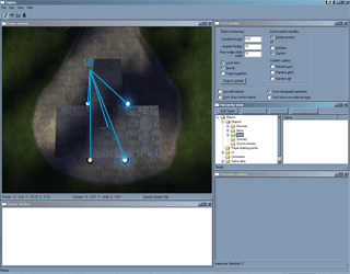
10) Add a Ghost vehicle to each base area. 

11) Just as with adding the Ghost vehicles, add a Warthog to each base.

The position and orientation of the vehicles can be adjusted just as with other objects.

The fourth image further explains the above procedures and shows the placement of the vehicle objects.


12)  The vehicles will now be assigned to teams or "sides".  In the Properties palette, enter a value of 1 under the "multiplayer team index" field for the Ghost and Warthogs at the Blue Base.

For the Ghost and Warthogs at the Red Base, enter a value of "0" in the "multiplayer team index" field.

A "multiplayer team index" of "0" denotes the Red Team or Red "Side"

A "multiplayer team index" of "1" denotes the Blue Team or Blue "Side"

The fifth image further explains the above procedures.


The vehicles will now be set up to appear only in certain game modes. 

The vehicle setups will be that the Ghosts and Warthogs are allowed in all game modes.

13) To set the vehicles up in this manner follow the procedures below:

a) Select the individual vehicle and go to the Properties palette.

b) At the bottom of the Properties palette are a series of check boxes under the "multiplayer spawn flags" section.

c) Enable the check boxes for the following:

slayer allowed
ctf allowed
king allowed
oddball allowed

The selected vehicle can now appear in Slayer, CTF, King of the Hill and Oddball based game modes or game variants.

NOTE:  The Race game mode is not included in this list.  The Race game mode and vehicle setup is handled completely different and will be covered in the Netgame flags section below.

Apply these settings for all 4 vehicles in the level.


The default vehicle configuration for the level will now be setup.

The vehicle defaults will be such that the Ghosts and Warthogs are present in all game modes but King of the Hill. The vehicles will NOT show up in King of the Hill by default, but can still be put in the level by the end user through the Multiplayer Options.

14) To set the vehicle default configuration perform the following procedures.  Select the individual vehicle and go to the Properties palette

At the bottom of the Properties palette are a series of check boxes under the "multiplayer spawn flags" section.

Enable the check boxes for the following:

slayer default
ctf default
oddball default

The selected vehicles will now appear in Slayer, CTF and Oddball based game modes or game variants by default.

Apply these settings for all 4 vehicles in the level.

The sixth image or last image further explains the above procedures.


Click to Open Larger Image in New Window


Click to Open Larger Image in New Window


Click to Open Larger Image in New Window


Click to Open Larger Image in New Window


Click to Open Larger Image in New Window


Click to Open Larger Image in New Window


Netgame Flags Placement

The objects that determine game rules and set objective points in the level are called Netgame Flags. 

These Netgame Flags are used to define the spot where a flag for CTF is located at, where the Oddballs in Oddball game modes spawn, the Race Points for Race Mode, the Race Vehicle spawn points, and the region or area for the control zone for King of the Hill. In addition, Netgame Flags are used to define the entry and exit points for teleporters.

For more information on the rules for Netgame Flags see the Multiplayer Level Design Technical Rules and Guidelines section under the General Level Design Information section located in the General Reference Sections.

The following section contains tutorials and examples that will demonstrate the placement of the Netgame Flags that are necessary for the proper operation of the level in a multiplayer game.


Placement of the netgame flags necessary for the Capture the Flag (CTF) game mode in the tutorial level:

1) Go to the Hierarchy view window.  In the Hierarchy tree expand the "Game data" branch. Next, select the "Netgame flags" branch/

2)  The netgame flags that will be added are ctf - flag objects.

In the Properties palette make sure the the "type" is set to "ctf - flag".

In the Game Window, press the Right Mouse Button to place a netgame flag object in the level on top of each base.

Align the netgame flag so that it matches the position of the previously placed "flag_stand.scenery" object.

3) In the Properties palette set the "team index" for each netgame flag.  This will determine the team setting for the flag.

The "team index" follows the "team index" conventions covered previously.

The "ctf - flag" netgame flag for the Blue Base should have its "team index" set to "1".

The "ctf - flag" netgame flag for the Red Base should have its "team index" set to "0".

The ctf - flag netgame flag represents the location where the flag will appear in the game as well as the area where the opposing teams flag must be taken to in order to score.

The image to the right further explains the above procedures.


Click to Open Larger Image in New Window


The following section contains tutorials and examples that will demonstrate the placement of a the Netgame Flags that are necessary for the proper operation of the Oddball game mode in the level for a multiplayer game.


Placement of the netgame flags necessary for the Oddball game mode in the tutorial level.

The next objects that will be placed are "oddball - ball spawn" netgame flags.

These spawn points act as the spawn point for the Oddball in the Oddball game types and game variants.  A level must have at least 1 Oddball spawn. 

The Multiplayer Game Options allow up to 16 Oddballs to be added to the game.

Levels can have multiple Oddball spawns up to and even past 16 Oddball spawn points. When more than 1 Oddball is set for a game type, the spawn locations are randomized.  When the Oddball is left sitting for too long, these spawn points are also used to randomly spawn the Oddball at one of the spawn point locations.

These different locations are denoted by an index.  For the "oddball - ball spawn" netgame flag the "team index" field is used as this index.

An index of "0" for the Oddball spawn denotes the primary or default Oddball spawn.

1)  In the Properties palette make sure the the "type" is set to "oddball - ball spawn".

In the Game Window, press the Right Mouse Button to place a netgame flag object on the small hill in the center of the level.

2) In the Properties palette set the "team index" for the netgame flag to "0".

3) Additional "oddball - ball spawn" netgame flags were added, 1 on top of each base, and 1 on each side of the level.

In the Properties palette set the "team index" for each netgame flag.  Number these sequentially.

The image to the right further explains the above procedures and shows the "oddball - ball spawn" netgame flag placement.


Click to Open Larger Image in New Window


The following section contains tutorials and examples that will demonstrate the placement of a the Netgame Flags that are necessary for the proper operation of the Race game mode in the level for a multiplayer game.


Placement of the netgame flags necessary for the Race game mode in the tutorial level.

The next objects that will be placed are "race - track" and "race - vehicle" netgame flags.

The "race - track" netgame flags mark the objective points to follow for Race game modes and game mode variants.

The "race - track" netgame flags use the "team index" to be set up in sequential order starting with "0".  When the last index is reached, the starting "race - track" netgame flag (team index 0) is next, creating the "race loop".

The "race - vehicle" netgame flags mark the spawn point for a vehicle to be used in Race mode.  Vehicles spawn based on the Multiplayer Game Options that are set for the race modes as well as the initial spawn locations of the player.  If a player spawns nearby one of these vehicle spawns at the start of a game, then the game uses the vehicle spawn point to spawn a vehicle near the player.

The number of player spawn points that are placed for Race mode and the number of "race - vehicle" netgame flags are 8 per team or "side" for a total of 16.  The netgame flags are set up like this in the event that all the players spawn on or near the same side.

If a level is not designed for vehicles (such as an indoor level) then "race - vehicle" netgame flags are not added.  The players will race around the level to the race points on foot, therefore the "race - track" netgame flags must still be added.


1)  In the Properties palette make sure that the "type" is set to "race - track".

In the Game Window, press the Right Mouse Button to place a netgame flag object on the small hill in the center of the level.  The "race - track" netgame flag was actually placed on top of the "oddball - ball spawn" netgame flag, this is valid.

Set the "team index" value for this netgame flag to "0".  This will be the first race point.

NOTE: The "race - track" netgame flags have a trigger field that forms a detection radius around the netgame flag.  Because of this, "race - track" netgame flags should NOT be placed at the exact same coordinates and instead should be staggered.  If the "race - track" netgame flags are not detecting the player or vehicle when they enter the field or run over the race objective, make sure the "race - track" netgame flags are not too close together, possibly interfering with each other when trying to detect the player.

2) The remaining "race - track" netgame flags were added at the following locations with the listed "team index" values:

Top of Red Base (team index 1)
Opposite side from the stream (team index 2)
Top of Blue Base (team index 3)
Middle of the stream (team index 4)

Since the level is so small, no "race - vehicle" netgame flags are placed.

The third image further explains the above procedures and shows the "race - track" and "race - vehicle" netgame flags.


Click to Open Larger Image in New Window


The following section contains tutorials and examples that will demonstrate the placement of a the Netgame Flags that are necessary for the proper operation of the King of the Hill game mode in the level for a multiplayer game.


Placement of the netgame flags necessary for the King of the Hill game mode in the tutorial level.

The next objects that will be placed are "hill - flag" netgame flags.

The "hill - flag" netgame flags are arranged such that they define a region that marks the control zone that the player must occupy in order to score in the King of the Hill game modes and game mode variants.  This control zone area is also denoted visually in the level when in a King of the Hill game mode.

The game basically connects all "hill - flag" netgame flags with the same index and forms a boundary zone.

The "hill - flag" netgame flags use the "team index" field to "group" the netgame flags together.

A "team index" of "0" indicates the main "hill".  This typically is the hill placed in the center of the level and is used for the King of the Hill game modes that do not move the hill location around.

In order to support the "moving hill" modes of play in King of the Hill, more than one control zone must be implemented.


1)  In the Properties palette make sure that the "type" is set to "hill - flag".

Set the hill index or the "team index" located in the Properties palette window to "0".

2) In the Game Window, press the Right Mouse Button to place "hill - flag" netgame flag objects in the form or a circle on the small hill in the center of the level. 

The first image further explains the above procedures.


3) Next, 2 more control zones were created to support King of the Hill games that use the "moving hill option".

The control zone at the Blue Base has "team index" "1" and the control zone at the Red Base has "team index" "2".

The second image or last image further explains the above procedures and shows the placement of the "hill - flag" netgame flags.


Click to Open Larger Image in New Window


Click to Open Larger Image in New Window


Teleporters instantaneously moves a player from one point in the level to another.  Teleporters only work for players and cannot teleport vehicles or other objects. The following section contains tutorials and examples that will demonstrate the placement of a the Netgame Flags that are necessary to create teleporters in the level.


Placement of the netgame flags necessary for the creation of teleporters in the tutorial level.

The next objects that will be placed are the "teleport from" and "teleport to" netgame flags.

For a teleporter to work 1-way, 1 "teleport from" and 1 "teleport to" netgame flag are necessary.  For a 2 -way teleporter an additional set of the netgame flags are necessary for a total of 4 netgame flags.

The "teleport from" and "teleport to" netgame flags use the "team index" field to "group" the netgame flags together.

Each teleporter netgame flag pair (a "teleport from" and "teleport to") index values must be unique.

1)  In the Properties palette make sure that the "type" is set to "teleport from".  This is the source or start point for the teleporter.

2) In the Game Window, press the Right Mouse Button to place the "teleport from" netgame flag object at the teleporter gateway at the rear of the Blue Base.

The netgame flag is placed close to the teleporter shield geometry to give the illusion that the player is teleporting when the shield is touched or approached.

3) Set the teleporter index or the "team index" located in the Properties palette window to "0".

The first image further explains the above procedures.


The "teleport from" teleporter source or origin netgame flag needs a target point.  The target point is the "teleport to" netgame flag.

4)  In the Properties palette make sure that the "type" is set to "teleport to".  This is the target or destination for the teleporter.

5) In the Game Window, press the Right Mouse Button to place the "teleport to" netgame flag object at the teleporter gateway at the rear of the Red Base.

The netgame flag is placed a slight distance away from the teleporter shield geometry to give the illusion that the player has just exited the teleporter field.

6) Set the teleporter index or the "team index" located in the Properties palette window to "0".

The second image further explains the above procedures.


The teleporter will now work 1-way.  Players can teleport from the Blue Base to the Red Base but not teleport back.

To allow the player to teleport from the Red Base to the Blue another set of teleporter netgame flags must be added.

7) The same procedures for steps 1-6 were followed to add a "teleporter from" netgame flag to the rear of the Red Base that targets a "teleporter to" net game flag at the rear of the Blue Base.

The "team index" for this set of teleporter netgame flags is "1".

The third image or last image further explains the above procedures and shows the placement of the "teleport from" and "teleport to" netgame flags.


Click to Open Larger Image in New Window


Click to Open Larger Image in New Window


Click to Open Larger Image in New Window


Netgame Equipment Placement

The objects that determine the placement of weapons and items (such as power ups) in a mulitplayer  level are called Netgame Equipment.

Netgame Equipment objects are attached to an "item collection".  An item collection is a data tag which can include a single weapon or item or a group of weapons or items.

Netgame Equipment objects can be customized per game mode.  Therefore, weapons and items can be customized by weapon or item type per game mode.

To see what single weapon and item, and weapon and item groups are available for placement, as well as what the .item_collection tag names are, refer to the tables located under the Weapons\Ammo\Items List section located under the General Reference sections.

The following section contains tutorials and examples that will demonstrate the placement of the Netgame Equipment objects in a multiplayer level.


Placement of Netgame Equipment objects in the tutorial level:

Unlike previous objects placed in Sapien, the Netgame Equipment objects do not have a palette.  The .item_collection data tags must be referenced for each item.

It is common to create one of each type of desired weapon or item in the level and then use these items to quickly create and place more items of the particular type.  This is similar to creating a palette but is a little more cumbersome.  This is done as mentioned before, select the item in the right pane of the Hierarchy view and then Right Mouse Click.

1) Go to the Hierarchy view window.  In the Hierarchy tree expand the "Game data" branch. Next, select the "Netgame Equipment" branch.

A health pack (which is considered a power up) will be placed in each base hallway for every game mode.

2) In the Game Window, click the Right Mouse Button to create a Netgame Equipment object in the middle of the Blue Base hallway.

3) In the Properties palette, click on the "..." button in the item collection field.  An Open dialog window will appear.

4) In the Open dialog window, go to the "item collections" tag directory under the main tag directory. 

Enter the "powerups" directory under the "item collections" directory.

5) Select the "powerup health  pack.item_collection" tag.

6) Once this is selected, hit Open.

NOTE: Netgame Equipment objects always appear as a marker.  The marker will never appear as the select weapon or item that is referenced from the .item_collection.

7) This item collection tag should now appear in the item collection field under the item collection area in the Properties palette.

8) The health packs will be available for all game types.

In the "type 0" field select the "all games" option by using the pull down menu.

Once the health pack is placed in the Blue Base hallway, add a health pack to the hallway in the Red Base.

The first image further explains the above procedures.


The next item that will be placed is an invisibility power up or "Active Camouflage" power up. 

This power up will appear in all game modes except for Race game modes.

9) To place the invisibility power up follow the steps below.

a)  In the Game Window click the Right Mouse Button to put down a Netgame Equipment object on the side of the level opposite of the stream.

b)  In the Properties palette, click on the "..." button in the item collection field.  An Open dialog window will appear.

c) Select the "powerup invisibility  pack.item_collection" tag in the Halo\tags\item collections\powerups" directory.

d) Once this is selected, hit Open.

10) This item collection tag should now appear in the item collection field under the item collection area in the Properties palette.

11) The health packs will be available for all game types except for Race mode.

In the "type 0" field select the "all except race_ctf" option by using the pull down menu.

In the "type 1" field select the "ctf" option by using the pull down menu.

The second image further explains the above procedures.


Weapons will now be added to the level.

The following weapons will be added for all game modes:

assault rifle    (assault rifle.item_collection)
flame thrower  (flame thrower rifle.item_collection)
frag grenade   (frag grenade.item_collection)
pistol             (pistol.item_collection)
rocket launcher (rocket launcher.item_collection)
shotgun          (shotgun.item_collection)
sniper rifle      (sniper rifle.item_collection)

12)  In the Game Window, click the Right Mouse Button to create a Netgame Equipment object behind the rock closest to the stream on the Blue Base side of the level.

13) In the Properties palette, click on the "..." button in the item collection field.  An Open dialog window will appear.

14) In the Open dialog window, go to the "item collections" tag directory under the main tag directory. 

Enter the "single weapons" directory under the "item collections" directory.

15) Select the "pistol.item_collection" tag.

16) Once this is selected, hit Open.

17) This item collection tag should now appear in the item collection field under the item collection area in the Properties palette.

18) The pistol will be available for all game types.

In the "type 0" field select the "all games" option by using the pull down menu.

Once the pistol is placed on the Blue Base side, add a pistol to the Red Base side in the same approximate location.

The third image further explains the above procedures.


The procedures above for steps 12 - 18 were followed to place the following weapons at the following locations:

1 assault rifle (assault rifle.item_collection) was placed in the middle on each side of the mound behind the trees.

1 flame thrower (flame thrower rifle.item_collection) was placed in the middle of the level in between the stream and surrounding hill.

2 frag grenades (frag grenade.item_collection) were placed in the center of the level on the mound side which is opposite of the stream.

1 rocket launcher (rocket launcher.item_collection) was placed in the center of the level on the mound side nearest the stream.

1 shotgun (shotgun.item_collection) was placed on each side behind the base near the teleporter gates.

1 sniper rifle (sniper rifle.item_collection) was placed on each side in the corners of the level behind the tree and rock formations.

The fourth image or last image further explains the above procedures and shows the final placement and orientation of the Netgame Equipment objects listed above.


Click to Open Larger Image in New Window


Click to Open Larger Image in New Window


Click to Open Larger Image in New Window


Click to Open Larger Image in New Window


Manipulation of Portals and BSP Elements


In addition to adding scenery objects and game objects into the level, Sapien can be used to manipulate the properties of the portals or clusters that exist in the .scenario_structure_bsp. These properties include the fog, ambient sounds, environmental audio, and weather effects.

For the tutorial level, the "Background sound" (ambient sound to play in the entire cluster or portal), the "Sound environment" (environmental audio effects to use for the portal or cluster), and the "Weather" (for this level, wind values) will all be set.

Fog settings for the level will not be applied since there are no fog planes or fog volumes in the tutorial level.

Atmospheric fog or "haze" has already been applied to the level due to the fact that these are set in the .sky data tag that is associated with the sky model or sky box for the level.

During the creation of a level, the core geometry can often change as well as the creation and modification of the portal geometry.  Any changes in the level mesh or portal geometry can cause the assignment of portal properties to be incorrect or reset to NONE.  The assignment of portal properties should be one of the last procedures performed on a level or should at least not be performed until the core geometry of the level and portal placement has been completed.

The following section contains tutorials and examples that will demonstrate the setup and modification of the portal or cluster data in the .scenario_structure_bsp for a multiplayer level.

The following section contains tutorials and examples that will demonstrate the application of Background Sounds to a portal or cluster.


Setting "Background sound" attributes in the .scenario_structure_bsp portals or clusters.

1) Go to the Hierarchy view window.  In the Hierarchy tree expand the "Cluster properties" branch. Next, expand the "Palettes" branch and select the "Background sound palette" subtree object.

2) Currently, the "Background sound palette" is empty.  To create a "Background sound palette" follow the procedures below.

a) Click on New Instance button in the Hierarchy view window.  A new instance of a background sound will appear in the right pane of the Hierarchy view window. 

b) Select this new instance.

c) This background sound instance must have a background sound now set. 

Go to the Properties palette and click on the "..." button located in the "background sound" section.  An Open dialog window will appear.

There are many sound tags available for use as a "background sound".  The majority of .sound_looping tags are located in the subdirectories found under the  Halo\tags\sound\sfx\ambience directory.  It is also quite common for individual level directories to contain their own custom sound directories that contain .sound_looping tags.  It is suggested that the user explore all the level directories to discover what .sound_looping tag resources are available.

3) Choose the a30 directory which is located under the Halo\tags\sound\sfx\ambience directory.

4) Select the "forest_day_wind.sound_looping" tag.

5) Click on the Open button.

This tag reference should appear in the background sound section in the Properties palette window.

6) This background sound reference must now be named.

In the "name" field in the Properties palette window enter the name "forest sounds".

The name should update in the right pane of the Hierarchy view window.

The name does not matter, it is just used for reference.  The background sound can be changed underneath this name.  This enables the generic "forest sounds" background sound instance to be applied to the portals or clusters in the level and then the actual background sound tag reference can be changed if needed to find the best background sound.

The first image further explains the above procedures.


The background sound will now be applied to all the portals or clusters in the level. 

7) Go to the Hierarchy view window.  In the Hierarchy tree expand the "Cluster properties" branch. Next, expand the "Palettes" branch and select the "Background sound" subtree object.

The portals or clusters should now appear in the Game Window.  The volume for a portal or cluster is outlined.  The currently applied "Background sound" is color coded for each portal.

8)  In the Tool Window, the "Render planes" and "Render non painted clusters"  check boxes can be enabled or disabled to help view the portals better.

Move the camera in the Game Window if it is not already clearly in a portal or cluster.

9)  The current background sound that is applied to the portal that the camera is in is displayed in the "background sound" pull down located in the Properties palette window.  In this case, "NONE" appears since no background sounds have been applied.

To apply the background sound to the portal, use the background sound pull down to select the "forest sound" background sound.  The background sound for the portal has now been set.

Move the camera to the next portal and repeat this procedure until all the portals in the level have the "forest sound" background sound set.

The second image further explains the above procedures.


Click to Open Larger Image in New Window


Click to Open Larger Image in New Window


The following section contains tutorials and examples that will demonstrate the application of "Sound environments" to a portal or cluster.


Setting "Sound Environment" attributes in the .scenario_structure_bsp portals or clusters.

1) Go to the Hierarchy view window.  In the Hierarchy tree expand the "Cluster properties" branch. Next, expand the "Palettes" branch and select the "Sound environment palette" subtree object.

2) Currently, the "Sound environment palette" is empty.  To create a "Sound environment palette" follow the procedures below.

a) Click on New Instance button in the Hierarchy view window.  A new instance of a sound environment palette will appear in the right pane of the Hierarchy view window. 

b) Select this new instance.

c) This sound environment palette instance must have a sound environment tag set for it.

Go to the Properties palette and click on the "..." button located in the "sound environment" section.  An Open dialog window will appear.

There are many sound environment tags available for use.  The .sound_environment tags are located in the  "Halo\tags\sound\sound environments" directory.

3) Choose the "sound environments" directory which is located under the "Halo\tags\sound" directory.

4) Select the "forest.sound_environment" tag.

5) Click on the Open button.

This tag reference should appear in the "sound environment" section in the Properties palette window.

6) This sound environment reference must now be named.

In the "name" field in the Properties palette window enter the name "forest environment".

The name should update in the right pane of the Hierarchy view window.

The name does not matter, it is just used for reference.  The sound environment can be changed underneath this name.  This enables the generic "forest environment" sound environment instance to be applied to the portals or clusters in the level and then the actual sound environment tag reference can be changed if needed to find the best sound environment.

The first image further explains the above procedures.


The sound environment will now be applied to all the portals or clusters in the level. 

7) Go to the Hierarchy view window.  In the Hierarchy tree expand the "Cluster properties" branch. Next, expand the "Palettes" branch and select the "Sound environment" subtree object

The portals or clusters should now appear in the Game Window.  The volume for a portal or cluster is outlined.  The currently applied "Sound environment" is color coded for each portal.

8)  In the Tool Window, the "Render planes" and "Render non painted clusters"  check boxes can be enabled or disabled to help view the portals better.

Move the camera in the Game Window if it is not already clearly in a portal or cluster.

9)  The current sound environment that is applied to the portal that the camera is in is displayed in the "sound environment" pull down menu located in the Properties palette window.  In this case, "NONE" appears since no sound environments have been applied.

To apply the sound environment to the portal, use the sound environment pull down menu to select the "forest environment" sound environment.  The sound environment for the portal has now been set.

Move the camera to the next portal and repeat this procedure until all the portals for the outside areas of the level have have the "forest environment" sound environment set.

10) A second sound environment is added to the "Sound environment" palette following the procedures above.

This sound environment is called "hallway environment" and uses the tag "hallway.sound_environment"

11) The "hallway environment" sound environment is set for the hallway portals in each base.

The second image further explains the above procedures.


Click to Open Larger Image in New Window


Click to Open Larger Image in New Window


The following section contains tutorials and examples that will demonstrate the application of "Weather" settings to a portal or cluster.


Setting "Weather" attributes in the .scenario_structure_bsp portals or clusters.

For the tutorial level, the weather effect that will be added is wind.  Wind affects certain objects, such as the contrail on the sniper rifle bullet as it travels and the waving of the flag used in Capture the Flag.

1) Go to the Hierarchy view window.  In the Hierarchy tree expand the "Cluster properties" branch. Next, expand the "Palettes" branch and select the "weather palette" subtree object.

2) Currently, the "weather palette" is empty.  To create a "weather palette" follow the procedures below.

a) Click on New Instance button in the Hierarchy view window.  A new instance of a weather palette will appear in the right pane of the Hierarchy view window. 

b) Select this new instance.

c) This weather palette instance must have a weather (.wind) tag set for it.

Go to the Properties palette and click on the "..." button located in the "wind" section.  An Open dialog window will appear.

Most multiplayer levels have their own multiplayer.wind tag file that exists in the root directory for the specific level.

For the tutorial, the multiplayer.wind file that will be used is an example .wind file that is included in the "tutorial_examples" level directory.

3) Go to the tutorial_examples level directory located under the "levels" tags directory.

4) Select the "multiplayer.wind" tag.

5) Click on the Open button.

This tag reference should appear in the "wind" section in the Properties palette window.

6) This weather reference must now be named.

In the "name" field in the Properties palette window enter the name "forest wind".

The name should update in the right pane of the Hierarchy view window.

The name does not matter, it is just used for reference.  The weather can be changed underneath this name.  This enables the generic "forest wind" weather instance to be applied to the portals or clusters in the level and then the actual wind tag reference can be changed if needed to adjust or select the appropriate wind and weather effects.

7) The wind direction and magnitude must now be set.  Follow the procedures below to enter these settings

a) In the "wind direction" settings enter a "3" in the "i" field.  The i, j, and k fields represent a vector.

b) In the "wind magnitude" field enter a value of "2".  This will be the strength of the wind in the direction indicated in the "wind direction" fields.

8) Notice that there is also a "particle system" section in the Properties palette window for the weather palette object. 


If rain or some other weather effect was needed in the level, this is the field where a particle system and associated tags would be referenced.

The particle system would be affected by the wind values set.

The first image further explains the above procedures.


The weather will now be applied to all the portals or clusters in the level. 

8) Go to the Hierarchy view window.  In the Hierarchy tree expand the "Cluster properties" branch. Next, expand the "Palettes" branch and select the "weather" subtree object

The portals or clusters should now appear in the Game Window.  The volume for a portal or cluster is outlined.  The currently applied weather is color coded for each portal.

9)  In the Tool Window, the "Render planes" and "Render non painted clusters"  check boxes can be enabled or disabled to help view the portals better.

Move the camera in the Game Window if it is not already clearly in a portal or cluster.

10) The current weather that is applied to the portal that the camera is in is displayed in the "weather" pull down menu located in the Properties palette window.  In this case, "NONE" appears since no "weather" have been applied.

To apply "weather" to the portal, use the weather pull down menu to select the "forest wind" weather system.  The weather for the portal has now been set.

Move the camera to the next portal and repeat this procedure until all the portals for the level have

the "forest wind" sound environment set.

The second image further explains the above procedures.


Click to Open Larger Image in New Window


Click to Open Larger Image in New Window


Saving the Level

At this point, the level should be saved. Anytime the objects in the level are touched, the .scenario tag should be saved.  The .scenario_structure_bsp data tag only needs to be saved when the data for the portals are modified. In the tutorials and examples above, all aspects of the level were modified, therefore both the .scenario and the .scenario_structure_bsp must be saved.

To save the level .scenario do the following:
1) Make sure that none of the portal or cluster groups are selected in the Hierarchy view under the Cluster properties group.  The option to save the .scenario tag will not appear if any of these groups are selected.
2) Go to File.
3) Click on Save .scenario
4) A message indicating the successful saving of the .scenario should appear in the Game Window.

To save the level .scenario_structure_bsp do the following:
1) Go to the Hierarchy view and select the Cluster properties group and expand the group tree. 
2) Select any of the portal or cluster groups.
3) Go to File.
4) Click on Save .scenario_structure_bsp
5) A message indicating the successful saving of the .scenario_structure_bsp should appear in the Game Window. The level data tags are now saved.


Conclusion to Population


The level has now has the necessary game objects in it and cluster settings that will allow it to run properly in Halo as a multiplayer level.Completed versions or example versions of the level tags that are created in the tutorial sections can be found under the "Halo\tags\levels\test\tutorial_examples" directory.  The completed tags have been provided as a reference to aid in the learning process. Once the user has successfully completed the procedures above they can proceed to the next section Running a Game Level in Halo.