|
|
Level Creation - Part 1 |
|
| The following section provides more detailed information on creating Multiplayer levels and environments and includes tutorials and examples. Topics covered in the tutorials include the creation of a level directory, creation of a reference frame, sealed world rules and explanation, the creation of a simple level, the creation of material and shader groups, the usage and application of materials and shaders, material and shader naming conventions, texture mapping, and miscellaneous and general tips and suggestions. |
| Getting Started |
|
Before editing or creating content for Halo please make sure to follow the set up and update information found in the section Creating a Development Environment. It is also recommended that the end user read through all the information found in the associated Reference Sections under General. A completed version or example version of the level created in the following tutorial sections can be found under the "Halo\data\levels\test\tutorial_examples" directory. The source and related materials have been provided as a reference to aid in the learning process. |
| Setting Up 3ds Max |
|
Make sure that the Blitzkrieg exporter plug-in for 3ds Max is installed, for more information see the Halo Editing Kit Installation topic under the Creating a Development Environment section. Each individual has their own style and settings that they prefer for 3ds Max the following are some suggestions and guidelines that may help with Halo editing. For additional information, please see the documentation that came with 3ds Max (associated manuals and in program User Reference under Help). The following are some tips and pointers for setting up 3ds Max for Halo content editing, specifically game environment creation. NOTE: All the setup suggestions were done using 3ds Max 5.1. Auto Backup It is HIGHLY recommended to enable the auto file backup features inherent in 3ds Max. This can save a lot of headaches and wasted time in lost work. To access the auto file backup features do the following: 1) Click on Customize and select Preferences 2) Click on the Files tab 3) On the bottom left click on the Enable check box under Auto Backup 4) Set the number of backup files and time intervals for the files to be backed up. 5) Hit OK It is also highly recommended that work be saved and saved often and that alternative backups be made of all relevant content Key Configuration Specific key configurations are not going to be listed here, but suffice it to say, if 3ds Max is being used as a level design tool it would be most beneficial to bind commonly used commands and operations for quick access. Some of the more commonly used commands that may not be as easily accessible with the default key configuration include Move Mode, Rotate, Backface Cull Toggle, Maximize Viewport Toggle, Rotate View Mode, and Zoom Mode. Configure Modifier Sets Just as there are several commonly used commands and operations that are used when creating and editing Halo game levels, there are also very commonly used modifiers. These modifiers include Edit Mesh, UVW Map, Unwrap UVW, and STL Check (used for checking if the level is a sealed volume and\or for finding open edges). Units Setup 1) Click on the menu option Customize and select Units Setup 2) Select Generic Units at the bottom 3) Hit OK The example levels, content, and other numerical information (measurements for various Halo related statistics such as player dimensions) were done using the Generic Units settings. View Port Configuration 1) Click on the menu option Customize and select View Port Configuration 2) Select the Layout Tab 3) Select the layout that suits you best, the example levels and tutorials use a 3 window layout with a 3d Perspective View at the top (Smooth and Highlight and Edge Faces turned on), Top Down View on the lower left and a Right\Left\Front view for the lower right window depending on the configuration of the level. 4) Hit OK |
| Creating a Level |
|
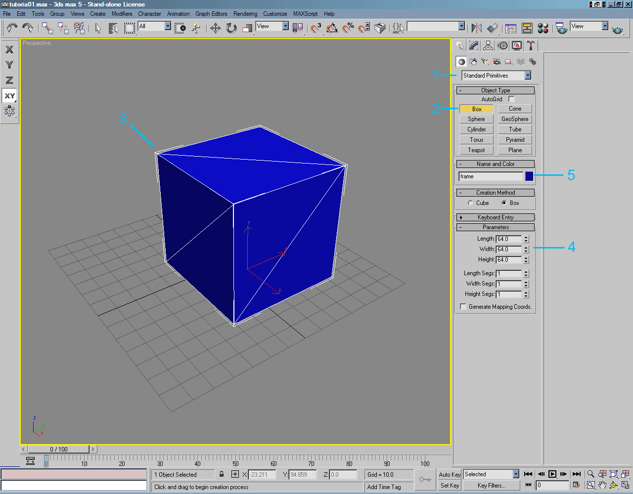
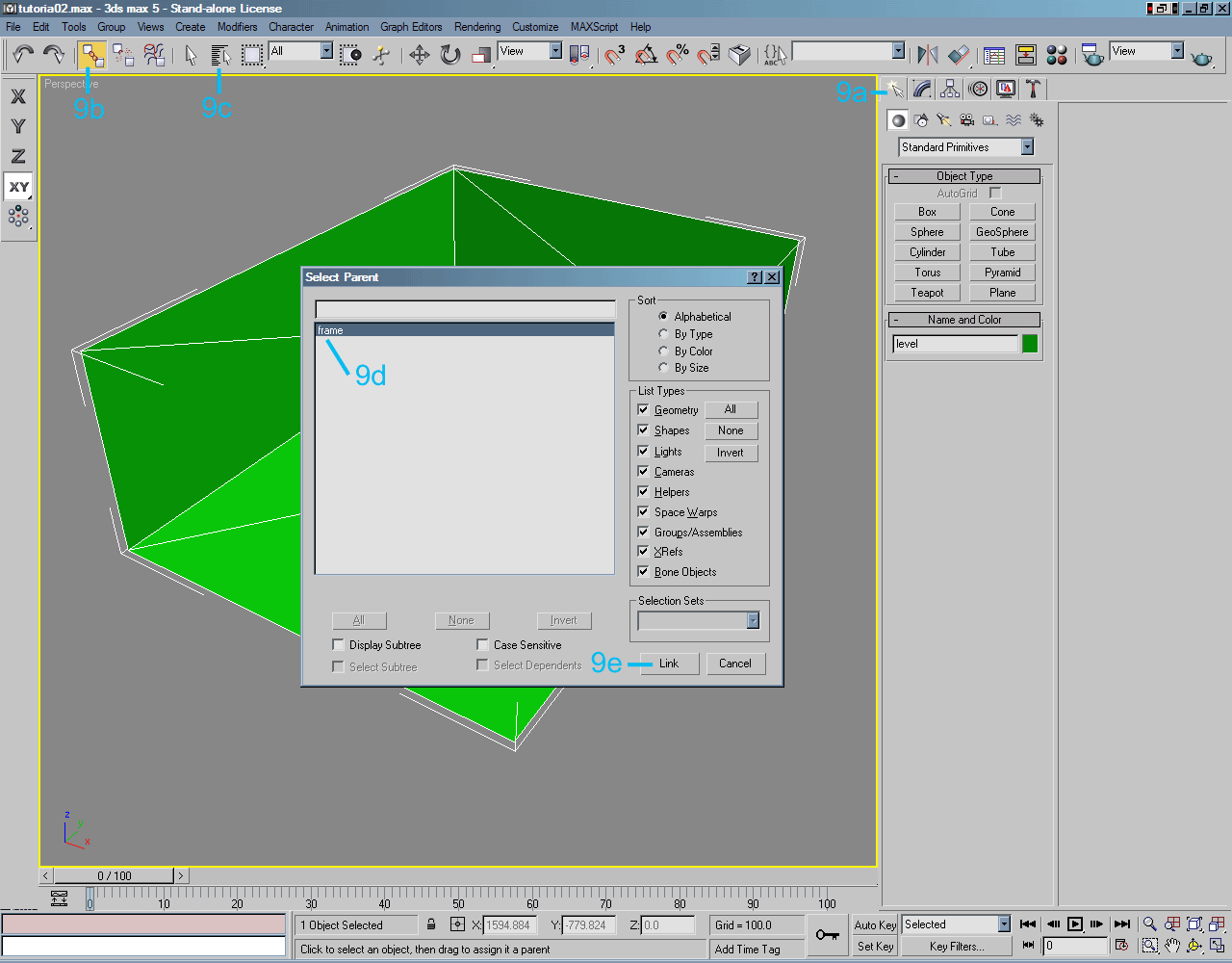
The following sections contain various information and examples that form one large tutorial that will go through the creation of a simple box level that will be used to demonstrate the construction of a Halo multiplayer level. Creation of a Level Directory The level directory will contain all the raw data or source files used in the creation of the level (.max, .tif, .psd, .jms, etc...). This level directory will have subdirectories. The main directory as well as the subdirectories are specifically used by the tools to compile the exported data formats into something that can be compiled into a .map cache file that is used to run the level in Halo. The name of the source directory must match the name of the exported .jms file (as will be explained later). The compiled data tags such as the .scenario and .scenario_structure_bsp tags that will exist in the tags directory will also share this name, as well as the .bitmap light map file once it is created by running the radiosity process on the level. The level directory name MUST BE UNIQUE, unless it exists under a totally different directory structure. As will be seen and demonstrated later, the level can pull shader tag information as well as other tag information from other tags that exist in other game level directories. The first step is to create a level directory under the level directory structure tree under the data directory in Halo. This level will be called "tutorial". Follow the steps below: 1) Under the Halo game directory (e.g. c:\Halo) create a directory called "data". 2) Under the new "data" directory create a directory called "levels". 3) Under the "levels" directory create a directory called "test". 4) Finally, under the "test" directory create the level working directory called "tutorial". The directory structure should now be as follows (if using the above example (e.g. c:\Halo)): c:\Halo\data\levels\test\tutorial Now that the level directory has been created, three subdirectories will need to be created that will contain the content source for the level. As mentioned previously, the tools recognize this directory structure during the compilation process of the level and of the .map cache file so it must be properly setup. Under the "tutorial" level directory add the following directories: 1) bitmaps (Using the previous example the directory structure would look like this: c:\Halo\data\levels\test\tutorial\bitmaps) 2) models (Using the previous example the directory structure would look like this: c:\Halo\data\levels\test\tutorial\models) 3) scenery (Using the previous example the directory structure would look like this: c:\Halo\data\levels\test\tutorial\scenery) The bitmaps directory is where .tif image files will be placed that can be compiled into .bitmap data tag files. The .tif image files in this directory can also be used for the displaying of the image on a surface in a level in 3ds Max (the .tif gets set as a Diffuse Map in the Sub-Material of a Multi/Sub-Object). The models directory is where the source files for the level mesh will be saved and where the .jms file used by tool to compile a level BSP data tag will be put. The scenery directory is where custom scenery model sub-directories and the associated resources will be placed. This is the level directory structure used by Bungie to develop Halo and is the directory structure that Gearbox adopted in order to keep the source tree consistent. It is also the directory structure that the tutorial and examples will use. NOTE: As will be seen later, when the data tags are created a directory and associated tags will be created or modified that mirrors the directory structure under data except this directory structure will be found under the "tags" directory under the root directory of Halo. In addition, when a .map cache file is created, the name of the cache file will be that of the main level directory structure used and will be found under the "maps" directory under the main or root Halo game directory. Creation of a Reference Frame A Halo level MUST have a reference frame. The reference frame is used as a reference point for the placement of objects in the level. Therefore, once the reference frame is placed and objects are placed in the level using Sapien, do not individually move the reference frame (or its associated polygons or vertices) or the objects will move or shift in the level. The reference frame is very useful during the construction of a Halo level. Any models or geometry that are not linked to the reference frame (the reference frame is considered the "parent") do not get exported when exporting out the .jms file using the Blitzkrieg plug in. This can make testing and debugging the level very easy. It also means that reference models (such as for players or vehicles) can be placed in the level and they will never get accidentally exported. It is also important to note that there must also be valid geometry attached or linked to the reference frame or the Blitzkrieg exporter will not export the .jms file and will give an error dialog "There was no geometry to export". Additional information on the Reference Frame and other technical rules or guidelines can be found under the Technical Rules discussion topic under the General Overview section under b>Multiplayer Level Design. A reference frame is very simple to create, the following steps and example images will demonstrate the creation of a reference frame. The reference frame is basically a box. It can be any size (larger is preferred to help with its selection and to make sure it does not get confused with other world geometry) and can even be a sphere, cone, cylinder or pyramid. As long as it is an object that is an enclosed volume. The reference frame should be created such that it does not interfere with editing and will not obscure parts of the level. For the example, the reference frame will be created such that it exists outside of the "northern" border of the example level. |
|
|
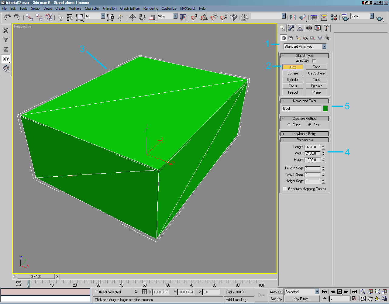
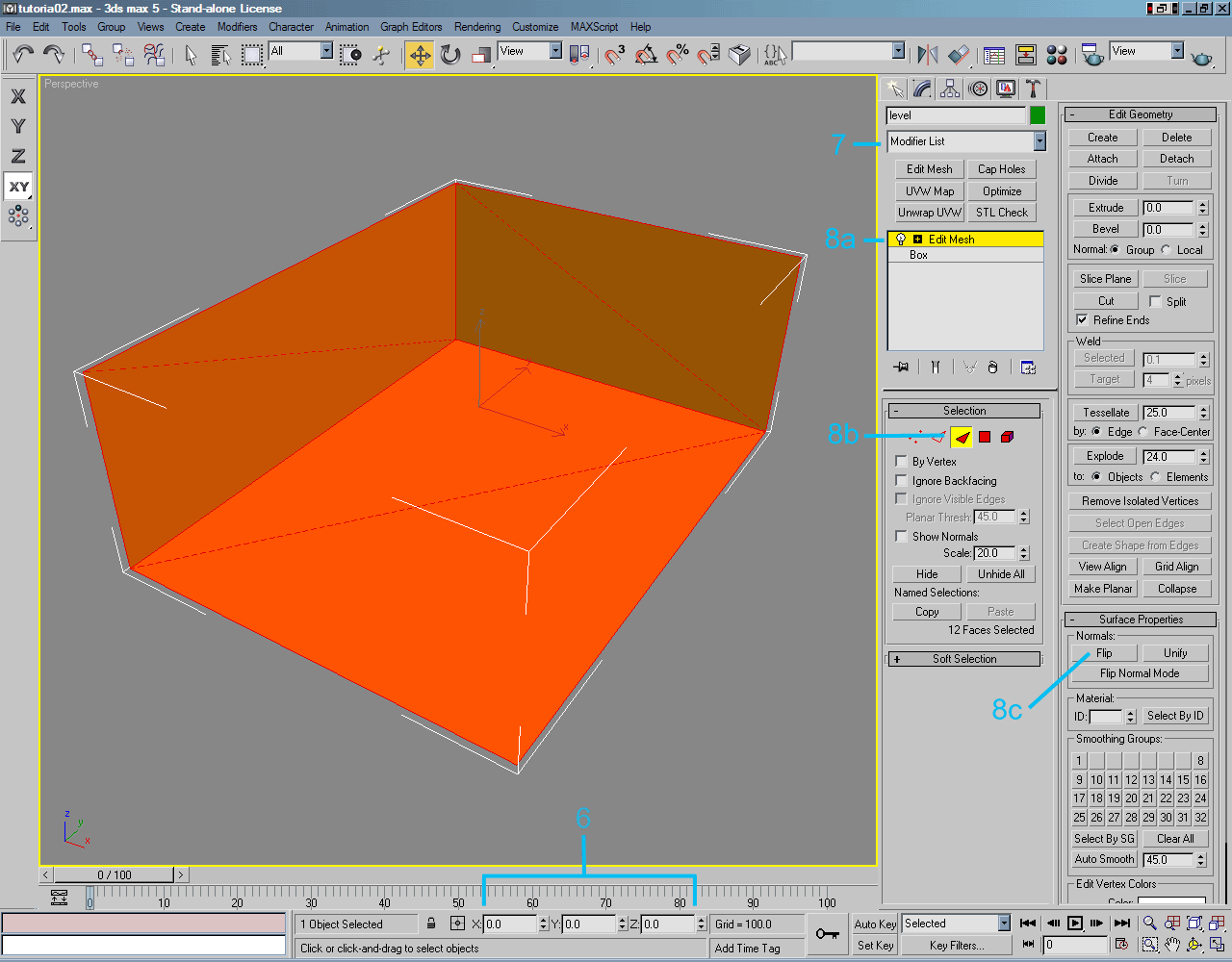
Creation of a Simple Level The following steps and example images will demonstrate the creation of a box that will serve as the tutorial level and will be utilized for all the subsequent tutorials. When creating or starting out a level try and keep the level centered at the origin. This can make the creation process much easier, such as when mirroring level geometry (such as team bases and other symmetric elements of the level). The level must be a sealed. The level must be a contiguous structure that forms a sealed volume, the following rules are referred to as the Sealed World Rules:
Additional information on the Reference Frame and Sealed World Rules and other technical rules or guidelines can be found under the Technical Rules discussion topic under the General Overview section under Multiplayer Level Design. |
|
|
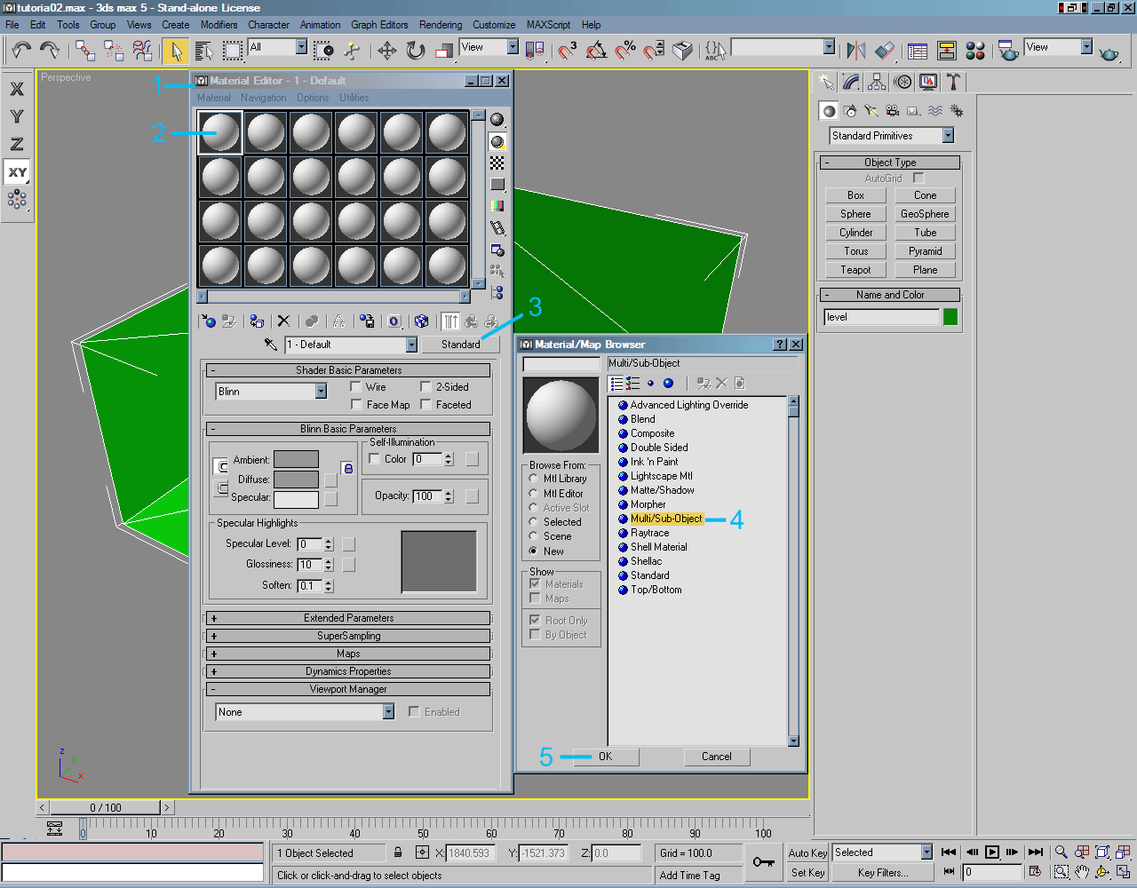
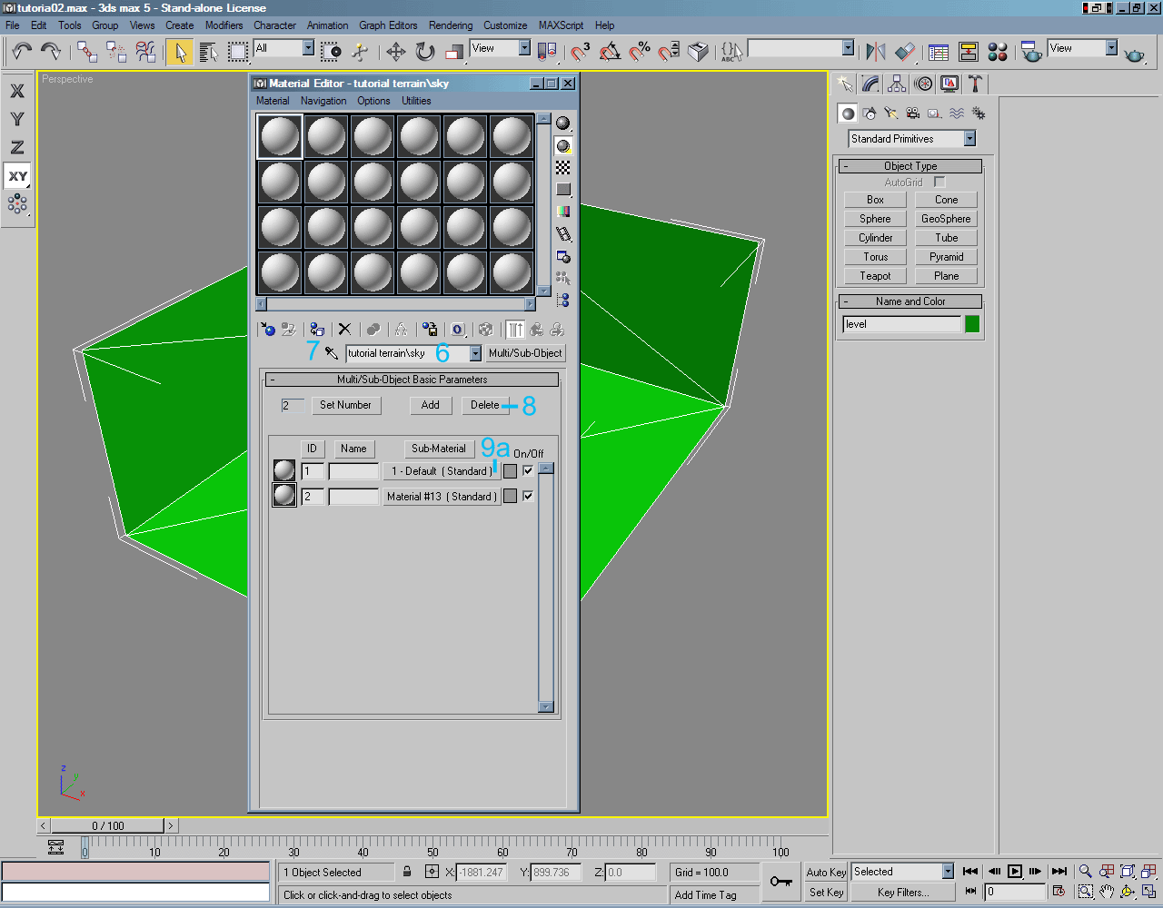
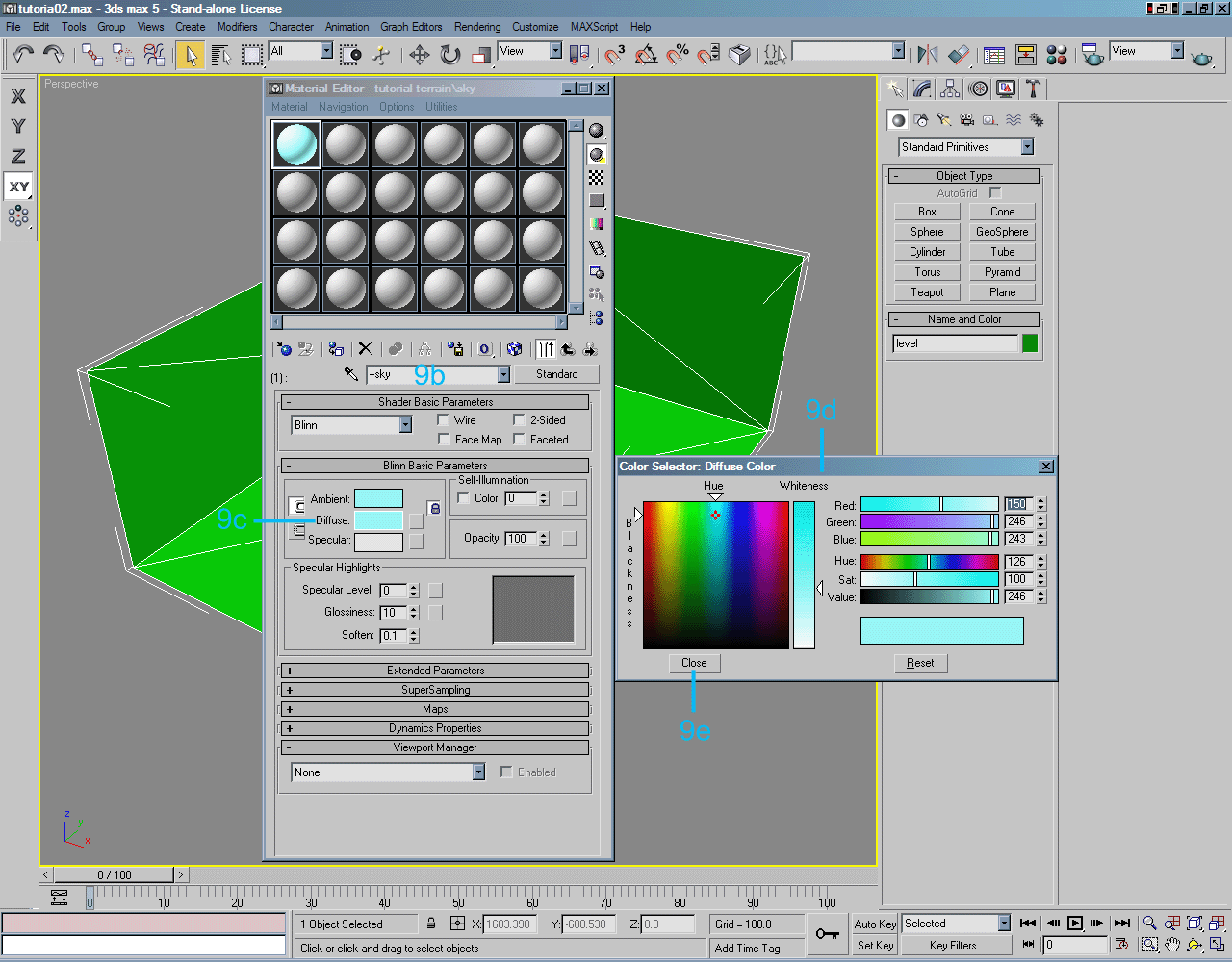
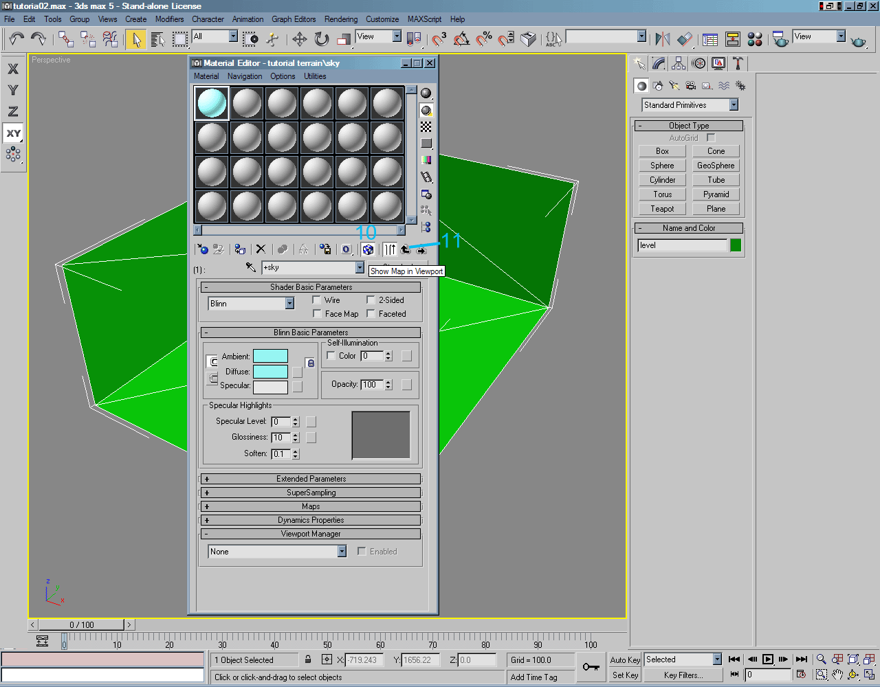
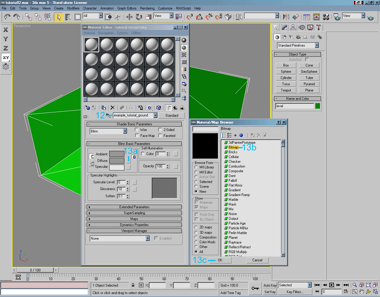
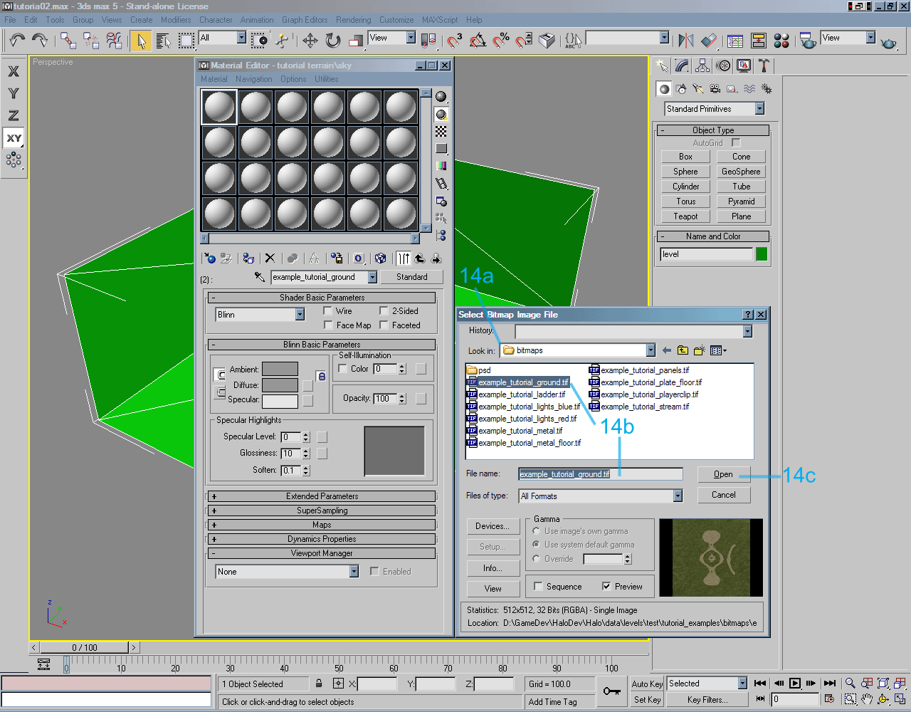
Application of Materials Before discussing and demonstrating materials and the application of materials to surfaces in the level, it is HIGHLY recommended that the Materials Overview section under the General Reference section be reviewed. The information contained in the Material Naming Conventions and Rules as well as the names of Special Materials and special Shader Symbols of this section will be referenced in the following examples. The following procedures and example images will demonstrate the creation of a Multi/Sub-Object material group and the creation, setup, and naming of the Sub-Materials under the Multi/Sub-Object material groups. The set up examples for Sub-Materials will include the linking of images that will be displayed in 3ds Max on the faces for the assigned material. These images are not absolutely necessary and no information related to these images are exported to the .jms file which is used by Tool to compile the level data tags. As previously mentioned, the Sub-Material name is important and is part of the data exported to the .jms file. This is the name that Halo will reference when assigning a shader to a particular surface. The referenced image in the Sub-Material can be any image, but it is usually the base map or base image (in the form of a .bitmap) that is referenced by the shader data tag. It is common for images to be used that are helpful in certain creation processes, such as displaying a grid texture to aid in the UVW Mapping process. Special Materials typically do not have images associated with them since they are primarily utility materials. Typically, just a material color or Diffuse color is associated with these Special Materials. Every face for the game level must have a material assigned to it (except for the Reference Frame as previously mentioned). |
|
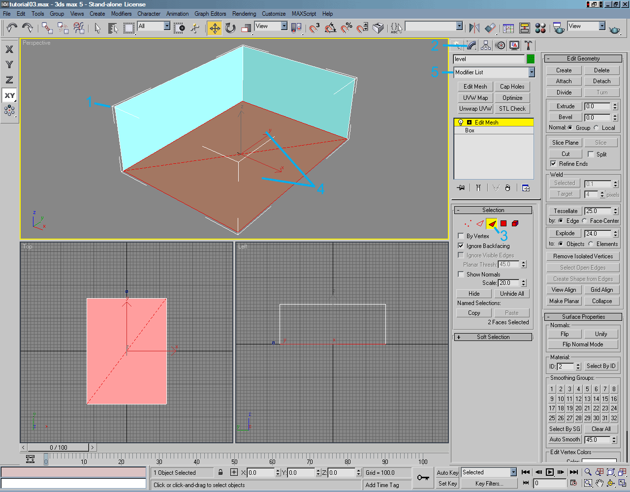
| The following procedures and example images will demonstrate the application of Multi/Sub-Object Sub-Materials to surfaces in the level. |
|
|
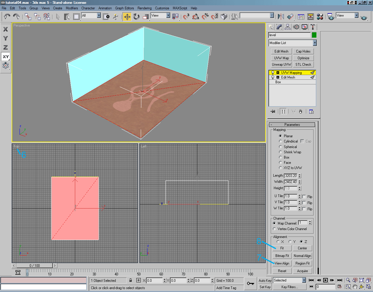
Texture Mapping With materials having been created and assigned to the faces that compose the level, certain faces must have mapping coordinates created for them. These mapping coordinates or "texture mapping" will allow the base maps or textures that are in the form of a .bitmap and are referenced in the shader data tag to properly display for the specific faces. Currently for the tutorial level, the only faces that need mapping coordinates are the 2 faces that compose the floor of the level. The other faces have the +sky special material applied to them which will tell Halo to render a sky model, these faces therefore do not need mapping coordinates. The following procedures and example images will demonstrate using UVW Mapping to apply texture or mapping coordinates to the 2 faces that compose the floor of the level. |
|
|
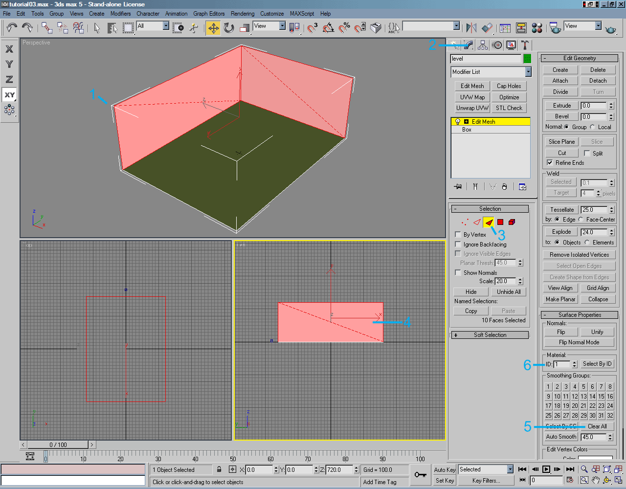
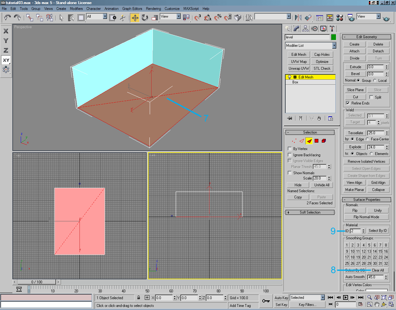
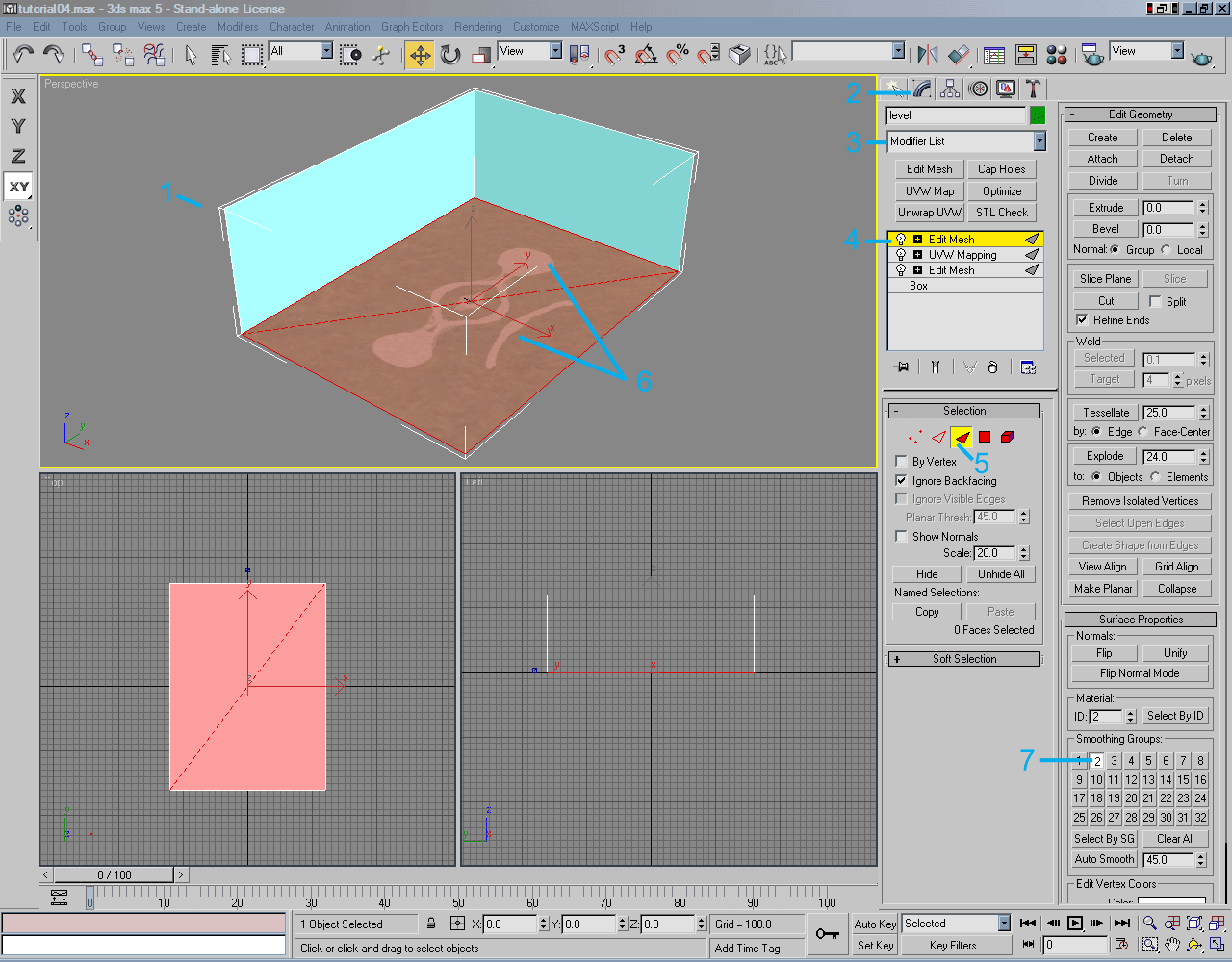
Assigning Smoothing Groups Smoothing group information is another piece of data that is actually exported from 3ds Max to the .jms file that is used by Tool to create the level geometry so that it can be run in Halo. Smoothing groups do not have to be applied but can greatly help in smoothing out the lighting on faces in the level. A good example is a 6-sided half cylinder used to create a pipe in a level. Without a smoothing group applied to all the faces that compose the sides, the cylinder will look faceted. With a smoothing group applied across these faces, the pipe will look much smoother and look to be made with many more polygons than it actually is. Smoothing groups can also help fix certain lighting errors or anomalies that occur across faces. It is important to note that the improper use of smoothing groups can cause as many visual effects and lighting anomalies on surfaces as it helps fix. Here are some simple guidelines for smoothing group usage: 1) Be careful over how much surface area a smoothing group is applied to. If visual anomalies occur it may be beneficial to split up the portions of the large geometry pieces to use different smoothing groups. 2) Try to keep smoothing groups unique. If there are several structures located throughout the level, each one should most likely have its own sets of smoothing groups applied to the faces that compose those structures. 3) Experiment with the smoothing groups for the best effects. Every level or surface tends to be unique depending on the lighting and construction. Currently for the tutorial level, the only faces that need to have smoothing groups applied are the 2 faces that compose the floor of the level. The other faces have the +sky special material applied to them which will tell Halo to render a sky model, these faces therefore do not need to have a smoothing group applied. Applying a smoothing group to the faces with the +sky material in 3ds Max to make things more viewable will not cause any problems in Halo. The following procedures and example images will demonstrate the application of smoothing groups to the 2 faces that compose the floor of the level. |
|
|
Saving the Level At this point, the level should be saved. To save the level do the following: 1) Go to File. 2) Click on Save As. 3) In the Save File As dialog window go to the Halo\data\levels\test\tutorial\models directory (this directory was created in the above section Creating a Level Directory) and save the file as "tutorial.max" by entering this name in the File name: field. 4) Click on Save. The level is now saved. This level will be used in the tutorial and example areas of the next sections. It may also be a good idea to make a backup of this file. |
| Conclusion of Level Creation - Part 1 |
|
At this point, the level could be successfully exported and compiled for use in the game. However, there are many other things that will be demonstrated that are useful in the creation of a Halo level.
The next section Level Creation - Part 2 will demonstrate some more aspects of Halo level design. If the user has successfully completed the above tutorials it is highly recommended that they proceed to the next section Level Creation - Part 2. For advanced users, or those that are curious or anxious to compile a level and get it running in Halo immediately, they may wish to skip ahead to the section Level Exporting followed by Level Compilation. Please note that the section Level Exporting and the subsequent sections will assume that the end user has completed Level Creation - Part 2 so the tutorials and example images will reflect the additions made to the "tutorial.max" file. |